Eng-Tips is the largest engineering community on the Internet

Intelligent Work Forums for Engineering Professionals

Lateral Stability for a Steel Structure

Status
Not open for further replies.

tristan861

Structural
Sep 14, 2015
77
0
0
JO
Hello Guys

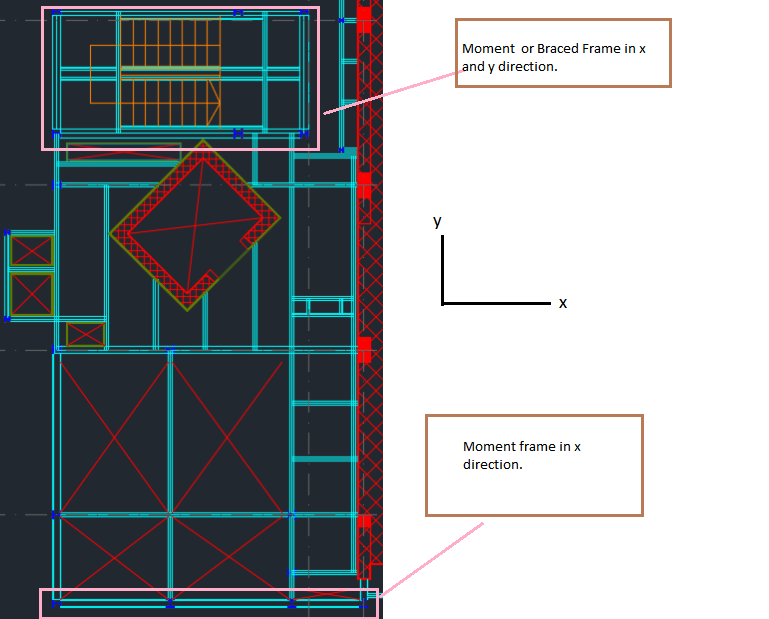
I have this steel structure plan view as the sketch shows. How do I handle with the lateral stability in this case?
As shown, in X direction most of the frames are supported by an existing concrete slab or shear wall. In Y direction some of members are supported by the shear wall.
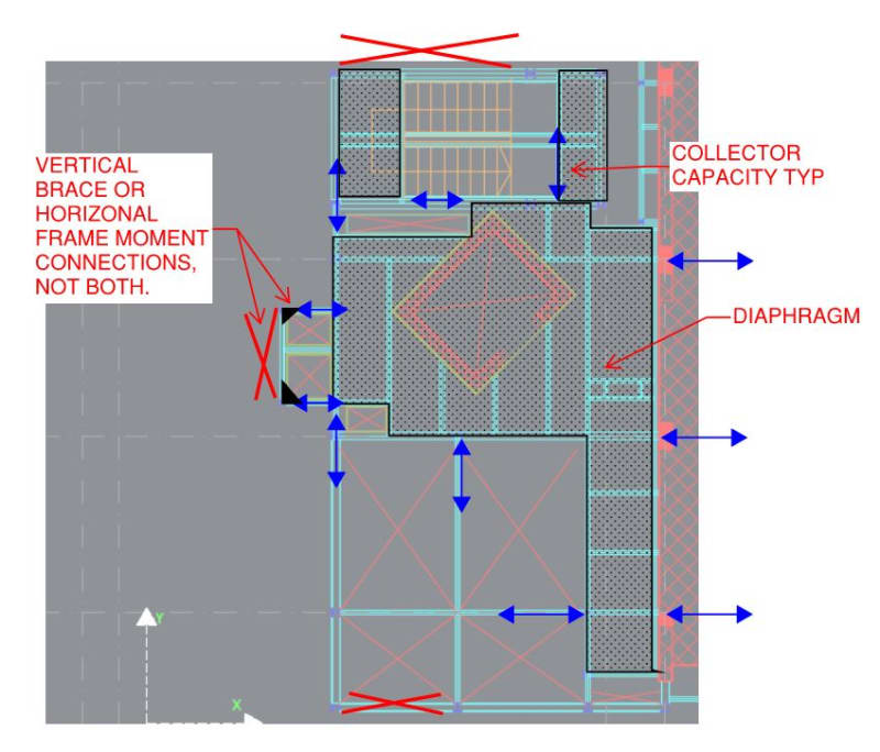
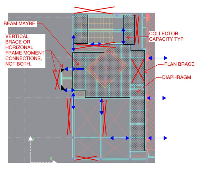
Can I release the moment in all beams and consider this structure laterally stable without adding v.brace or making moment frames?
Or should I deal with each frame separately and change the beam to column connection to a moment connection where it is not supported on a rigid element?

Note: Base plates are pinned connected for all steel columns.
 
 https://files.engineering.com/getfile.aspx?folder=ebcd6db9-be24-4add-8ec3-44f273500272&file=1121.PNG
Replies continue below

Recommended for you

Can you use masonry in-filled walls?

Rather than think climate change and the corona virus as science, think of it as the wrath of God. Feel any better?

-Dik
 
I don't see why you wouldn't be able to count on the shear wall if:

a) The horizontal bracing is sufficient to transfer the lateral forces from the unbraced side to the shear wall
b) The shear wall is sufficiently strong to support the full lateral force on the structure

If it were me I would just brace both sides. I take it you aren't using a matrix structural analysis type program to design this structure?

“Any idiot can build a bridge that stands, but it takes an engineer to build a bridge that barely stands.”
 
No. It is an open structure.

Then, wouldn't it be considered as a "lean to" structure, which relies on the stiffness of the supporting structure to its right. I would say "yes, it is possible".
 
Of course it is possible, the challenge at hand is to prove it. Is there a reason you don't want to add bracing in the y-axis opposite of the shear wall?


“Any idiot can build a bridge that stands, but it takes an engineer to build a bridge that barely stands.”
 
We don't have a complete picture/knowledge on the structures, its use, and type of loadings it subjects to. For instance, the supporting structure is quite flexible, and wind or seismic load is likely control the design.... MegaStructures said better then.
 

Yes it is possible.. provided that the floor deck ( composite deck?) will serve the diaphgram action for lateral stability. The connection of deck to the lift shaft and shear wall shall be detailed to transfer the horizontal loads..
 
Tristan how are you analyzing the structure? It sounds like you might be doing this by 2d frame analysis? I would really want to use a 3d analysis procedure to verify that it's ok to have asymmetric bracing.

“Any idiot can build a bridge that stands, but it takes an engineer to build a bridge that barely stands.”
 
HTURKAK

Unfortunately, the deck is not composite and no adequate space for H. brace due to the required openings.

MegaStructures
Im using 3D analysis using FEM.


I decided to not count on the shear wall alone. As you can see, multiple systems might be there (braced and moment frames).
I forgot to mention that the structure is around 65 ft height consisting of 5 floors similar to this one.

Should I worry about the asymmetrical bracing? would it induce additional torsion/ eccentricity on the building for example?

Here is the plan view again. I really would like to know your opinions.
Thanks alot,,

Capture_x17y0p.png
 
Like many of these questions there just isn't enough detail to give an answer.

Of course the left side need to be laterally restrained. Either braced in elevation, braced in plan to restrain it on the shear wall or moment framed. The best course of action depends on the needs of the structure. Moment framed could give you issues with differential deflection compared to the stiff shear wall.

I am puzzled by the existing in plan cross bracing. It seems a bit arbitrary. But of course I only have 10% of the picture so there might be some good reasons for that approach.
 
op said:
How do I handle with the lateral stability in this case?

I've made a lot of assumptions here but this is how I might approach your situation. I sense that this is an industrial structure which often means:

1) You definitely want competent stability bracing and;

2) Diaphragms are often ineffective and/or non-continuous so some concessions to pragmatism must be made.

Obviously, adding in some more bracing is only going to improve stability and, perhaps, constructability. What I've show for bracing below is my practical minimum.

C01_ohiamw.jpg
 
At the other end of the spectrum, you could spend a few extra bucks to do something like this and then be almost independent of diaphragm action, both during erection and in service.

c02_cxkche.jpg
 
Status
Not open for further replies.
Back
Top