Eng-Tips is the largest engineering community on the Internet

Intelligent Work Forums for Engineering Professionals

Lateral system for row houses 6

Status
Not open for further replies.

SleeplessEngineer

Structural
Jul 12, 2020
46
0
0
US
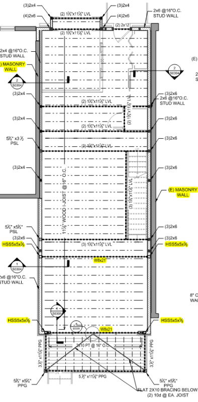
I am not very familiar with residential buildings and wood construction (only been working in this area for 3 years, so forgive me if the answer is so obvious). This is what I have done for a single-family row house rear and one-story addition (20'x50'). For the short side, there is not really any shear wall segments that can be used for design due to the large opening in the rear wall. I have added 2 steel moment frames. The GC is not happy and argued over an hour and talking to the owner about engaging another engineer to redesign. He was arguing that in 20 years of his experience, no one asked for steel moment frame in single family. So, this got me thinking, am I missing some exceptions in IBC for row houses? As far as I know, row house should be designed independently for lateral forces (not allowed to rely on adjacent structure). Any tips or ideas for more economical solution will be appreciated. If I am indeed over-engineering, I would like to change ASAP. Otherwise, I don't mind losing clients. Thanks for reading.
img ]
 
Replies continue below

Recommended for you

How are the row houses organized? Are they individual owners with separate titles or is there a strata / co-op / HOA thing that collectively owns the structure with interests for each of the individual owners? The former would be individual structures with zero setback to the property line. The latter would be potentially combined structures.

 
They are all individual owners. No HOA or any collective organization; they can modify or even completely raze as they like. So, it's the individual structure. It is designed as individual.
Not sure how others get away with it. I have checked someone else's calculation for similar case of wood wall rear addition; they mentioned 'by inspection it is ok' in their calculation report. And it's a mid-size company who does lot of big projects too.
 
SleeplessEngineer said:
He was arguing that in 20 years of his experience, no one asked for steel moment frame in single family.
Classic contractor comment. I personally had two single family projects with steel moment frames last year, and I know my boss has specified moment frames many times over the years for this exact kind of situation where you don't have any usable shear wall segments to preclude a large cantilever in the diaphragm. Could you maybe look into Simpson Strong-Walls? It looks like you have a bit of wall width to work with at least at the bottom frame. Strong-walls can be surprisingly narrow, but also are still expensive.
 
I am not sure about the one question (whether this single unit is not allowed to use the lateral capacities of the neighboring houses). It makes sense. But I've never done row houses.

I have had an experience where the owner wanted pretty much the entire wall completely open (no shearwalls). I came up with a solution. But I don't know if you can use it in your situation.

1. I decided to load everything on the available floors and roofs. So, the first floor which was completely open didn't load anything.
2. The second floor wall would transfer to the second floor (diaphragm) and the roof (diaphragm).
3. The two diaphragms would then be treated like cantilever beams.
4. The other available walls (which act as flanges on an giant I-beam) would take the load and transfer it to the ground via diaphragm action.

Be very careful. You need to verify that you have enough strength, length, and stiffness. Otherwise, it is just a house of cards.

I my situation we had an internal wall that was far enough away from the empty wall that we were able to beef that up enough to handle the shear.
 
With the desire for more open plan living designs, and large often full length wall openings, steel beams (for open plans) and moment frames (for lateral) are becoming much more common in housing. I've done them in my own designs and seen them in others. Typically around here they are portal frames made from steel channel (200-300mm deep)
 
Lomarandil said:
This means nothing.
I know what you mean. But we still have to compete with them for projects. If even bigger companies don't really ask them for much, it is difficult to convince clients why we actually need them. The argument yesterday turned how I dont't know how make the structure optimal just using wood walls.

plausibly_civil said:
Could you maybe look into Simpson Strong-Walls?
We have tried that for few projects. It requires the wall segments to be same width at all level; for some reason, our projects don't ever align up. Everyone hates this more than steel frame since it is expensive also longer lead time.

Althalus said:
I decided to load everything on the available floors and roofs.
Not sure if I follow you right. I presume you are just talking about open front structure.
 
You're in the wrong code, for one, it sounds like it's International Residential Code. There's language in there for structural independence for townhomes, and yes, when they can demolish the one in the middle they all need to support themselves.

Short answer: NO, they all need a viable lateral system that meets IRC or is designed to engineering standards. Even if it were under the building code the same thing would apply. There's a lot line effectively between all of these units. Unless there's something really atypical going on here, i.e. there's an architect involved, they are all on a common foundation, and they have a unified set of fire design details to be an aggregate structure somehow, (I mean two hour fire walls or maybe more between the units).

If you can justify the individual unit as a rigid diaphragm that would enable the open front, potentially. If we are talking wood construction.

The reason the contractor has "never seen this" is because he's using the wrong engineers.

"By inspection it is okay," these folks need to be reported to the board. To me, this is not appropriate and it not the standard of care, either. This is hand waving where we are expected to do calculations. (See other thread: Several of those disciplinary actions involve "designs" with no calculations behind them.)

For further reading -
Heathman Disciplinary action, Minnesota, 2010

Also, I don't see your plan dimensions, but there are limits on wood floor and diaphragm aspect ratios. They didn't give you any realistic options here with that front and back elevation, you don't have a real rigid diaphragm option unless you somehow get a shear wall in the middle of the building running left-right. And I'd rather not mix a 2x4 stud wall and a 2x6 stud wall along the same line of force, considering the top plate is a discontinuous mess, and that's the diaphragm collector for the North south direction.
 
I think I read in structure mag an article about using semi rigid diaphragms and 3 sided braced walls for open front structures, iirc it was for steel though. Would depend on your seismic loads if this is feasible or not though, and some pencil sharpening of course.
 
Three sided structures are fine and pretty normal. You use the pair to take the eccentricity of the unpaired wall in the other direction. This one looks like it doesn't have a place for a shear wall at all in one of the directions, so you can't do that. You can move the moment around reasonably easily to get stability, but the shear needs to go somewhere.
 
lexpatrie said:
You're in the wrong code
It's a 4 story above grade; so, IBC. Open front structure never really worked for any of our projects so far. Arch wants open space; they don't give us any interior stacked wall to help us. On other hand, GC always complains why we did not use wood wall instead of moment frame. So stuck between them

 
Not really, you owe a duty to the public to design a safe structure, you're not strictly in the business of making the client HAPPY. That's what all the language about "when your decisions as a Professional Engineer are overridden and create a public danger...." are about.

As to the three sided diaphragm, look at the plan, there's not much structurally on the north and south sides of the drawings so it's a box but there's no third side.

Layout_nikvbj.png


@Canwest - Most likely you mean this article?:
Tackling the 3-Sided Box Diaphragm: One Engineer’s Perspective, Lintz, Structure Magazine, Feb 2002.

If you really want to call their bluff, have them hire a peer reviewer. If the peer disagrees with you, well then. They have a new guy to defectively design their buildings and you know who he is. ("When your decisions as a Professional Engineer are overridden and create a public danger...")

As to the IBC, it would seem there's likely a fire wall between the two occupancies, then 706 and 706.2 show up, most likely. If one side collapses and the other side has to not collapse, that sounds pretty similar to the structural independence that shows up in townhouses in the IRC.

2018 International Building Code, Chapter 7
 
Ah yeah, I didn't actually see the plan attached to the first post since they are usually attachments, just going off the description. Moment frames it is
 
Well you could do a steel braced frame and run the braces through the doors and windows. Or perhaps a flying buttress on the outside?

I don't see a lot of feasible options besides a steel moment frame. I suppose a cantilever column system could be entertained, but it's just an upside down moment frame, with extra foundation.

ETA - I don't see a second moment frame though, so this is a three sided "open" diaphragm that has some aspect ratio issues to deal with as well. Open front structures are subject to a lot of limitations in the SDPWS.
 
If you're doing a moment frame, you could put just one in the middle to minimize eccentricity and then use the diaphragm to take out the balance. So, use the three sided building idea but locate the lateral system to minimize the eccentricity you need to deal with. That being said, you could likely put it anywhere if your entire side walls are potentially shear walls. You've likely got lots of capacity.

You could also see if you have enough space to use one of the Simpson Strong Wall portal frames if that optically feels better to your client.


Or buy enough space to get some strong wall panels in
 
The limitations on cantilever (wood) diaphragms need to be respected, however. An "H" shape, as you describe it, could work, but there are limitations on the aspect ratio of the diaphragm. If the building is long enough, it would need a sort of double crossbar H to keep the aspect ratios within limits. The drawing above doesn't have dimensions...

Nobody has name-checked Terry Malone's book, yet. The Analysis of Irregular Shaped Structures Diaphragms and Shear Walls. Second edition now.

The Analysis of Irregular Shaped Diaphragms, Malone, Woodworks, June 2015.

I don't see a W8x21 beam as offering much in terms of deflection control especially when mated to an HSS column, and the two moment frames are way on the bottom of the page, so there's a pretty big cantilever toward the top of the page. Aspect ratios are also questionable.
 
I don't even really do diaphragms and I bought Terry Malone's book after I saw excerpts here. It's great compared to the really handwave-y treatment that diaphragms seems to get in a lot of literature.

Irregular diaphragms are in the same class of design problem as irregular concrete reinforcing detailing where a lot of people seem to ignore resolving forces and load paths on a local level.
 
lexpatrie said:
The limitations on cantilever (wood) diaphragms need to be respected,
[bowleft]
YES!

TLHS said:
It's great compared to the really handwave-y treatment that diaphragms seems to get in a lot of literature.
[bowleft]
Absolutely!

Much of my general understanding of the common treatment floor/roof diaphragms has come from this forum as my area of work has not often used them. So from that context the lack of an explicit following of the diaphragm load path has often left me scratching my head.

Sure a decent and well connected diaphragm can be quite stiff and strong. But a blanket assumption that is ALWAYS such is seems a little cavalier.

I won't claim to have all the wisdom. But I'm a mostly steel guy, I don't often use diaphragms and if do I treat it with a healthy degree of caution.
 
There are circumstances where ignoring something isn't "harmful," but you are (negligently) relying on luck and chance and ignoring the basic principles of mechanics.

If the diaphragm isn't designed to 0.99 without regarding the complexities and convolutions in the load path, there's potentially some reserve strength in the diaphragm to "find" a load path. So, hypothetically if you don't do a rigorous analysis of the load path if you keep a 50 plf excess capacity in the diaphragm it may work fine, if there's a load path and the results of that stress concentration is less than 50 plf.

It's kind of like Wooten's third law.....

Wooten's Third Law, Modern Steel Construction, Second Quarter 1971. As a side note, it's a bit of a scream to me that James Fisher, Design!, Modern Steel Construction, April 2006, references this article but gets the year wrong.

At minimum these are failures in the design community that "we" bake into the design process, these sorts of ethical/technical lapses that are "only on paper" will not always show up or cause damage in structures.

And to some extent there's complacency in the engineering field that's either trained in to the new people by the experienced engineers who at least partly bank on the structure never experiencing the design loads.

Ed_note_May_2006_fj6ksf.jpg

(that link doesn't work..., but it does seem to download a blank wooten.pdf..)
 
Status
Not open for further replies.
Back
Top