Continue to Site

Eng-Tips is the largest engineering community on the Internet

Intelligent Work Forums for Engineering Professionals

  • Congratulations KootK on being selected by the Eng-Tips community for having the most helpful posts in the forums last week. Way to Go!

Least material condition applications in this drawing- help! 1

Status
Not open for further replies.

zsa

Mechanical
Dec 1, 2016
22
Screenshot_2022-08-30_150727_nc7rtd.jpg

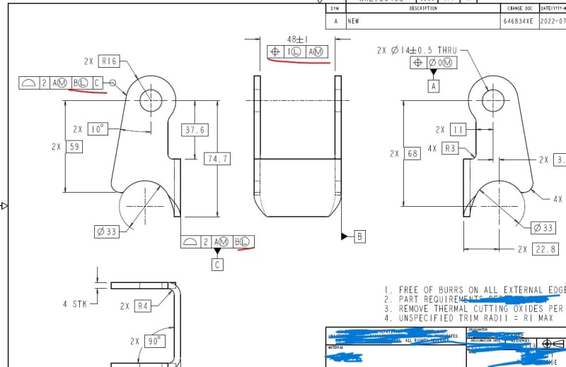
Hello! I am having a little bit of trouble trying to understand /decipher the least material condition and its affects on this diagram. the underlined width of 48+-1 with a LMC modifier,not sure what this means physically? the wdith of the part with a poisition tolerance is the tolerance for the center plane between those two faces but what does this mean when it has the LLC modifier ?

Also, how does the LMb on datum B play into the profule tolerance called out?


can someone please help me out here?
 
Replies continue below

Recommended for you

Probably datum feature B symbol should be aligned with 48±1 size dimension to make sense of B being modified at LMB (2009 terminology)
Moreover, relationship between A and B should be perpendicularity (not position|1LMC|A(MMB)|)

zsa said:
Also, how does the LMb on datum B play into the profule tolerance called out?
Will offer you some datum feature shift/ datum feature mobility. Additional rocking in the datum feature system, but you cannot see it in a physical datum feature simulator (gage), only seen by a software/ CMM since it is an inside material measurement idea

 
zsa,

MMC and LMC are only meaningful on a feature of size, such as datum[ ]A. Datum feature[ ]B appears to be a flat face. It cannot have an LMC.

--
JHG
 
drawoh, agreed, but it is called out on the dimension 48+-1 which is a feature of size and that is what i am kind of struggling to grasp. this is a planar featuree of size so the position tolerance here would be on the center plane between the two faces that the dimensions lines point towards so how does the LMC come into play here and what doe sit mean/signify?
 
Y14.5 doesn't have an interpretation for a single planar surface as a feature of size. Placing that datum feature symbol where it is shows that datum feature B is a single planar surface. To use the width, the datum feature symbol must be placed in line with the dimension or with arrows pointing to the two surfaces like a dimension would to be in compliance with the Y14.5 interpretation.

It looks like a weldment detail. I guess it's a clevis or hinge part that fits inside another part.

The profile FCF that establishes datum feature C does not benefit from calling out datum feature B as the part is fully constrained with the axis of datum feature A.
 
3DDave,

Yes it is a kind of hinge.

My question about the 48+-1 still stands:

The 48+-1 dimension is a feature of size and the FCF placed underneath it means that this planar featuree of size has a position tolerance? What does that look like physically? I guess one aspect of my question is that I have not dealt with true position of a planar feature of size and am not sure how to visualize/understand what this looks like.


Second aspect of my question is how does the LMC come into play for the 48+-1 dim with regards to the cylindrical tolerance zone for the center plane between the two faces?and what doe sit mean/signify?

 
It can not be positioned to datum feature A, so there's that, at least not in Y14.5 territory.

If it was a perpendicularity control, then there would be a center plane idealization that the half-way points of all opposing points on the part would have to be within a width centered on that center plane and the width would be 1 wide + whatever narrowing of the feature at that location was.

Because this applies at LMC, if the part was 49 and perfectly parallel**, then the middle of the pair of surfaces be mis-oriented (again, if it is changed to perpendicularity) within a 1 wide zone that is perpendicular to the datum A datum simulator/true geometric counterpart axis. If it was 47 and the sides perfectly parallel they could be mis-oriented within a 1 + 2 wide zone relative to datum A simulator/true geometric counterpart axis.

Confounding this is that datum feature A axis doesn't have to align with the datum feature axis because of the (M) modifier. Instead the datum simulator/true geometric counterpart axis can rattle around in the holes according to the size of the holes.

**It's weird because LMC is obvious for holes and slots that are carved into bulk material but it doesn't match with this case as it takes more material to create that separation.
 
zsa,
As others indicated, perpendicularity should have been used instead of position to control the 48+/-1 width with ref. to datum feature A.
It is applied at LMC and there are actually two possible methods to verify conformance to this control.

One is called the surface method, and it requires that the feature doesn't invade a boundary inside the material, of a width that equals to 49(the LMC size)+1(the perp. tolerance at LMC) = 50 mm, which is perfectly perpendicular to the datum axis derived from datum feature A. This method is the one that represents the design intent of such specification better. Perpendicularity at LMC is used when there is a need both to orient a feature of size relative to a datum, and maintain some limit beyond which material should not be removed or absent.

The other supported interpretation is related to controlling the center plane for fitting between two parallel planes tolerance zone oriented perpendicular to the datum. It's a bit problematic because there is a slight difference between related ASME standards with regard to how to obtain that center plane, but considering the design intent I described above (ensuring enough material at the sides of the slot) and what now clearly specified in the new standard on measurement data reporting (ASME Y14.45) the controlled center plane for an internal width (slot) is the center of two parallel planes of the minimum separation, that will contact the lowest points on the two actual surfaces (this means the planes for the center plane derivation are inside the material). In the Y14.5 language, it is called the "unrelated actual minimum material envelope". See an illustration in this link. The size of the tolerance zone is dependent on the size of the actual slot, but more precisely, it is dependent on that same "unrelated actual minimum material envelope" as described above. So, when this envelope's width is equal 49 the tolerance is 1 mm as specified in the feature control frame. You get more tolerance ("bonus") as the envelope becomes smaller, and that means 2 mm of perpendicularity tolerance for 48 mm size, and 3 mm tolerance for 47 mm size (the specified 1 mm plus the amount the feature's envelope is smaller than the LMC limit).
 
What Burunduk was trying to say is that the Virtual Condition boundary of the opening is 50 mm (49 mm is the LMC + 1 mm for the perpendicularity and that the related surfaces of the part shall not exceed the Virtual Condition boundary. This is what the surface method is about.

Unfortunately this LMC Virtual Condition boundary is in solid metal and cannot be expressed with fixed gauging elements. It can only be confirmed on a CMM, at which point the centerplane (Y14.5-2018 is weak on this and says "axis method") can be determined directly without comparing it to the Virtual Condition boundary.

I would like to see the next assembly and see how the geometric controls applied at that level related to those at this one.

 
I was not trying to say this - I said this. Knowing that not everyone is fluent in Y14.5 terminology I didn't replace the geometric description with a term Virtual Condition.
 
3DDave said:
Unfortunately this LMC Virtual Condition boundary is in solid metal and cannot be expressed with fixed gauging elements. It can only be confirmed on a CMM, at which point the centerplane (Y14.5-2018 is weak on this and says "axis method") can be determined directly without comparing it to the Virtual Condition boundary.

Contrary to what this might imply, A CMM measurement is not ought to be performed by the centerplane/resolved geometry method. If material condition modified tolerances always required fixed gaging, there would be no surface method for LMC. It is possible to inspect it by CMM per the surface method. And the centerplane determination is not more direct for such control in any sense.
 
Yet you didn't use the very term that the standard does as a requirement for the surface interpretation - it's literally the basis for the surface interpretation. In fact, you clearly did not say it.

Very bad form to mislead people when the standard defines it.

There cannot be fixed gauging for LMC, regardless. Both methods require a CMM.

What does "not ought" mean?

In order to find out by CMM if it meets the requirement per the surface method one first needs to make the measurements and calculations required to determine the centerplane, at which point the surface method is no longer required, hence it is direct, rather than continuing on to indirectly seeing if the surfaces are within the Virtual Condition boundary.
 
Screenshot_2022-09-01_155059_oupu9n.jpg


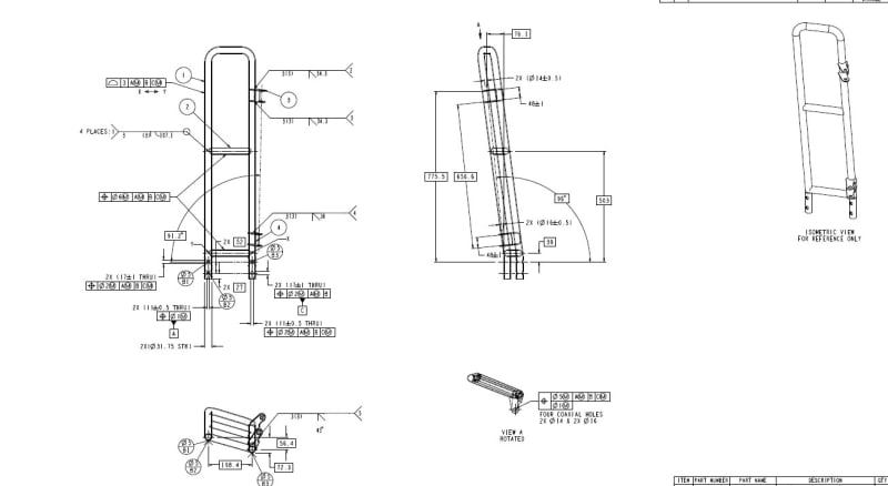
This is the top level assembly drawing if that helps. Items 3 and 4 re of interest. These are support brackets( that also act as some sort oof pivot hinge i believe)
 
3DDave,
I didn't use the term Virtual Condition but I used general terms which are very similar to the ones the standard uses to define the VC. What I said conveys the idea. The OP can find the exact terms in the standard by looking up LMC controls. My explanation aids him in getting the general idea by using regular vocabulary.
Recently in another thread you insisted that for certain companies it is a good idea to ignore dimensioning and tolerancing standards and instead have their engineers writing notes to explain everything. Obviously those notes would be in general terms. Funny that all of a sudden you have something against explaining an idea without using "the very term that the standard does". Can't make up your mind?

"Very bad form to mislead people when the standard defines it"

I don't do misleading. It is your responsibility and what you do best:
"If it was a perpendicularity control, then there would be a center plane idealization that the half-way points of all opposing points on the part would have to be within a width centered on that center plane"
Half-way points of opposing points?? Are we talking center plane control or symmetry?

And after that you pretend to clarify my explanation, by throwing in the term VC. If the person who asked the question knew what the VC is for, he wouldn't ask the question in the first place.

In order to evaluate conformance by the surface method, it is necessary only to simulate the LMC VC and the related actual minimum material envelope. If the latter is smaller than the former for the slot, the feature is conforming. There is also no need for a center plane for the measured value calculation when the surface method is used. When CMM can simulate these two envelopes, this is everything that's required. Anything else is indirect.
 
zsa,
It is hard to distinguish the exact interface between the brackets and the other components from the assembly drawing,
But if the bracket component drawing defines the finished part and something fits inside width 48, it would make more sense to control it at MMC.
 
It's a bit fuzzy but I see no benefit to using LMC. Maybe it's trying to control the outside of the part using the inside??

On the assembly the use of MMC to control the locations of the cross pieces (and for other part controls) requires the assembly drawing to show what the Maximum Material Condition of the item is - like a note of what the maximum diameter is. This is regardless of being a detail on the same drawing; there is no guarantee that a part that is welded will remain as straight and not be deformed by the process. If the cross-piece is on another drawing then that's a default requirement. It's OK to repeat dimensions and tolerances at a different level of the drawing - it's not a duplicated or redundant dimension to do so.

Lots of other things that look weird. The main thing is this - one should be able to create the primary datum feature wearing a blind-fold to the rest of the part. Often this is done by picking a big flat surface that the raw stock comes with.

In this case, datum feature A is just two holes drilled at some relatively random location and without regard to angular rotation around the wall of the tube. Now this won't likely result in an acceptable part - almost surely none of the features that depend on datum A will be where they should be, but that's back-driving acceptable locations of datum feature A and is a bad practice. It can result in accepting unusable parts.

I can't really decide on what should be done without the entire next assembly and so on, which is far too much, but it seems like there needs to be a rethink on the whole tolerance and datum selection process.

I think I would start with datum targets on the formed tube to lock that main feature into a datum reference frame and then add most of the other features relative to that reference frame.
 
zsa,
The more I look at the component and assembly drawings, the less the component drawing makes sense.
We assumed that datum feature B was intended to be a width type feature of size but that is not what the drawing shows. It clearly shows a planar surface datum feature in a manner that looks fully intended (not like a result of a sloppiness).
We assumed that the position tolerance applied to the 48 width dimension should be perpendicularity and it has no locational function, but it is not what the drawing shows.
The answers you got are based on guesses and "ifs".
You should talk to whoever made or supplied this drawing and have him explain the design intent and the requirements.
 
Status
Not open for further replies.

Part and Inventory Search

Sponsor