human909
Structural
- Mar 19, 2018
- 2,112
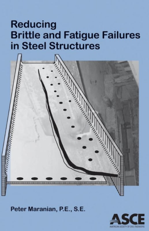
Does anybody have some good references on understanding and dealing with fatigue failure in steel? As I understand it is exacerbated by cyclical stress (obviously) particularly high stress or alternating compression-tension stress.
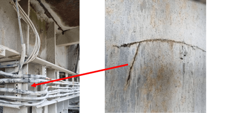
I ask as I will be looking at this bottom flange & web crack.
I believe it is in an area of hogging moment but likely with enough vibration for it to cycle through compression and tension. It is loaded by heavy vibratory equipment.
I ask as I will be looking at this bottom flange & web crack.
I believe it is in an area of hogging moment but likely with enough vibration for it to cycle through compression and tension. It is loaded by heavy vibratory equipment.
![[rednose]](/data/assets/smilies/rednose.gif "[rednose] [rednose]")
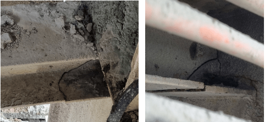
![[smarty]](/data/assets/smilies/smarty.gif "[smarty] [smarty]") I believe I've answered my own question by a clue in another grainy photograph supplied. This beam isn't a gravity beam, it is a horizontal member as part of the lateral support system. The system is x-braced compression members so is quite indeterminant. That area could be under quite high tension depending on the way the structure is loaded. (Also this structure supports some very heavy vibrating machinery so the cyclical cause doesn't need to be chased down.)
I believe I've answered my own question by a clue in another grainy photograph supplied. This beam isn't a gravity beam, it is a horizontal member as part of the lateral support system. The system is x-braced compression members so is quite indeterminant. That area could be under quite high tension depending on the way the structure is loaded. (Also this structure supports some very heavy vibrating machinery so the cyclical cause doesn't need to be chased down.)