Continue to Site

Eng-Tips is the largest engineering community on the Internet

Intelligent Work Forums for Engineering Professionals

  • Congratulations KootK on being selected by the Eng-Tips community for having the most helpful posts in the forums last week. Way to Go!

Lifting column design

Status
Not open for further replies.

Pimech

Mechanical
Nov 7, 2012
27
Dears, I’d like to read your advises/ experience regarding the size of a lifting column.
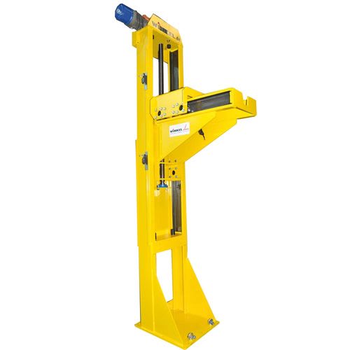
I’m designing a lifting column made with two beams (rectangular steel tubes); there are two linear guide rails fastened to the beams and a plate that can go up and down trough a lead screw driven by an electrical motor. The plate is a sort of vise that hold a weight.
Is possibile to fasten a linear guide rail directly on a rectangular tube?
I’m mainly interested in sizing the two beams (suggestions on modifications are welcome) and the plate connected to the ground.
The weight is approximately 1,5t, the arm e is 500mm and the height of column is 2200mm.
Thank you
 
 https://files.engineering.com/getfile.aspx?folder=1bd77f96-5e84-4d61-8bd1-75888076465f&file=3A8B494F-2458-4845-BDFE-299F691C6A64.png
Replies continue below

Recommended for you

Something like this ?
csm_H3-Spindelheber_03_b8e3fc8533_n8pizw.jpg
 
Yes, something similar.
I could use stiffeners like in the picture.
 
"Is possible to fasten a linear guide rail directly on a rectangular tube?"
Possible? Yes. Successful? No. Why? Because the straightness of the surface of most raw steel products is not good enough for the requirements of precision linear rail. If you attached your rail directly to the surface of the steel you will be inducing error and non-linearity into your rails. All the major linear rail manufacturers offer engineering guidelines on the recommended methods to obtain a good mounting surface. If you're starting with standard steel rectangular tube you will have to weld a flat bar on the surface you intend to use, put it through a stress-relieving process to relieve all internal stresses from welding, and then machine it to the straightness and flatness recommended by your rail manufacturer.​

"I’m mainly interested in sizing the two beams and the plate connected to the ground." Analyze the forces involved at each linear bearing and that will guide your design process. Make sure you have adequate bearing separation to prevent binding or galling.
 
Hi Pimech,
What precision in motion do you need for this mechanism? Some linear rails for 1.5t are going to be expensive. I have succefully attached supported round linear rail to a welded assmebly of 4x4 tubing. A lot of care was put into making sure the weldment was as straight as possible and the installation of the rails was done by sliding the mechanism up and down and fastening the rails in turn to make sure the distance between them was always the same.
For sizing the beams, refer to general beam theory and Free body diagrams. Look at shear and bending moment at worst case position of the load. Pay attention to any local web crippling that may occur as a result of the point load on the beam from the moment of the arm. Maybe not an issue if your linear rails distribute the load enough.
Size connections according to your loads. Probably the columns will be welded at thier base, so important to size that weld group.

Hope this sets you in the right path
James

 
Jboggs said:
f you attached your rail directly to the surface of the steel you will be inducing error and non-linearity into your rails. All the major linear rail manufacturers offer engineering guidelines on the recommended methods to obtain a good mounting surface. If you're starting with standard steel rectangular tube you will have to weld a flat bar on the surface you intend to use, put it through a stress-relieving process to relieve all internal stresses from welding, and then machine it to the straightness and flatness recommended by your rail manufacturer.

Yes. It was a my doubt. I'm evaluating to use STANDARD COMBINED ROLLER BEARING with C profile rail. I think they required less precision on mounting surface.

James Kevin Marks said:
What precision in motion do you need for this mechanism? Some linear rails for 1.5t are going to be expensive. I have succefully attached supported round linear rail to a welded assmebly of 4x4 tubing. A lot of care was put into making sure the weldment was as straight as possible and the installation of the rails was done by sliding the mechanism up and down and fastening the rails in turn to make sure the distance between them was always the same.
I don't need particular precision. I'm finding alternative solutions, like C profile I mentioned previously. Have you an example of round linear rail and slides or pictures/sketches of your applications?

Thank you all!
 
"standard combined roller bearing ..." : You could use the profile/system of the fork lift
 
Status
Not open for further replies.

Part and Inventory Search

Sponsor