Eng-Tips is the largest engineering community on the Internet

Intelligent Work Forums for Engineering Professionals

Lifting Mechanism Force Analysis

Status
Not open for further replies.

roshane87

Mechanical
Mar 14, 2015
21
0
0
LK
Hi Everyone,

I am in the process of designing a lifting mechanism for a conveyor and I'm struggling to get my head around the reaction forces at the pivoted joints.

Could someone please help me find out what R1x R1y are please ?

Any tips would be most welcome.

image_rx7jbq.png


image_pxqvni.png


RN
 
Replies continue below

Recommended for you

roshane87, no idea what you are trying to do. Lift the whole thing? Is "x" a force? The unlabeled vertical arrow is a what? No dimensions where any of these forces, if they are forces, are acting.

See this all the time. Nice model, no useful information.

Suggest you revisit your statics textbook. From the start.

Regards,

Mike

The problem with sloppy work is that the supply FAR EXCEEDS the demand
 
those two inclined links are two force members (force is axial). So R1x/R1y is known by geometry.
This says immediately that there is a 3rd (pivot) point constraint ... or the links aren't parallel ?

are you lifting on the upper "strap" ?

does the conveyor run over this ramp, left to right ?

can you draw a free body ?
start with static weight only,
then what loads are added when the conveyor belts starts to run over it ?
then what loads when you try to lift the ramp ?

another day in paradise, or is paradise one day closer ?
 
How many points are you lifting on? If you are lifting on R1 and R2 then as RB1957 states the links are two force members and can easily be found, however there is a link slightly to the right of the arrow marked M with a red arrow going vertical what is this?
If you are lifting on three points then it becomes a statically indeterminate problem.

“Do not worry about your problems with mathematics, I assure you mine are far greater.” Albert Einstein
 
I thought he was lifting with the up arrow (at the top of the pic), reacting this with the two lower links.

is the ramp pivoting about some point ??

My mind stopped when I noticed the two links have the same slope so a vertical force applied will cause an unbalanced Fx ??

another day in paradise, or is paradise one day closer ?
 
Well I thought the two pivot points were R1 and R2 which he wanted help with however I have no idea what that upward arrow is indicating but I'm not trying to guess, hopefully the OP will inform us in due course.

“Do not worry about your problems with mathematics, I assure you mine are far greater.” Albert Einstein
 
Hi Everyone,

Apologies for the confusion regarding the arrow up but as the subject says, the purpose of this arrangement is to lift the conveyor up from the tank it sits in for cleaning purposes.

Therefore the arrow up indicates where the lifting force will be applied to lift the conveyor up. This will be by means of a chain.

The 2 linkages I circled on the video attached are to help lift the conveyor evenly off the floor of the tank it sits in. There will be 4 linkages in total - Front Left, Rear Left, Front Right, Rear Right. What you can see circled are Front and Rear Left.

The tank itself is flat at the back but inclines 15 degrees up to follow the shape of the conveyor. The picture shows the conveyor lifted off the tank floor, hence the gap between the tank floor and conveyor.

What I need help with is to calculate the size of the pins and linkages required to support this approx 1250kg conveyor while it's lifted around 400mm off the tank floor. For that, I need to calculate the reaction at the pin joints on the tank floor. However, I can't work out if I'm missing a horizontal component of any force acting on the pinned joints. After that, I can apply double shear and single shear equations to the pins.

M is the Mass of the conveyor. X is the distance to the center of Gravity of the conveyor from the Rear Pivot Point. R1 is the reaction at the rear pivot point and R1x & R1y are its horizontal and vertical components. Again, the arrow up indicates the lifting force that will be applied to lift the conveyor evenly off the tank floor by means of the linkages.

Hope this makes more sense now. Looking forward to your replies.

RN


RN
 
 https://files.engineering.com/getfile.aspx?folder=994327ac-bcd2-4119-9efc-a18c2bcf82b0&file=Backward_Sim_2.wmv
Hi roshane87

Thanks for the video, in effect looking at the video the linkages as RB1957 stated are two force members, this means the forces can only transmit along each of the linkage lengths in a straight line and the force they transmit will be proportional to the distance from the centre of gravity of the mass and the angle of the linkages which will be different during the lifting movement.
You need to do a kinematic analysis of the lift, ie you draw the linkages at different angles as they would be during the lift, at each angle say steps of 5 degrees you can take moments about one of the pivot points to find the forces at the other pivot point. I will try and explain this further later.

“Do not worry about your problems with mathematics, I assure you mine are far greater.” Albert Einstein
 
Hi roshane87

Right having looked at the video earlier and initially thought that you could calculate the reactions by taking moments, well sadly you can't because there are to many unknowns, now if the red arrow drawn going upwards which is lifting the device coincided with the centre of gravity M going down then you have reduced the problem to two unknowns and can solve it by taking moments. As it stands at the present if I take moments about the right hand pivot I have two unknowns the first being the value of the force in the red arrow going vertically upward and the second being the force in the left hand link, so its statically indeterminate as it stands.

“Do not worry about your problems with mathematics, I assure you mine are far greater.” Albert Einstein
 
Hi desertfox,

Thank you for your quick reply.

As you may have noticed this is a machine that I am currently designing so I realize some things while designing. The Pulling Force (F) will be at an angle so it will also have 2 components. We can also assume F passes through the C of G or is very close to it therefore when taking moments at the Right pivot distance to F would also be X.

I've attached an updated diagram which I hope will help solve the problem a bit easier. I know the angles A & B will vary but if I can put together the equations required using symbols, then I can swap numbers and try and see the highest values where failure would likely occur.

image_jyhfa4.png


RN
 
Hi

There are to many unknowns to solve statically as it stands at present, think of a normal simple supported beam, you usually know the applied load but you have to calculate the beam reactions, you can do this by taking moments about one of the reactions because doing this reduces the problem to one unknown and the applied load and therefore it’s solvable by statics, you can’t do that in your case.

“Do not worry about your problems with mathematics, I assure you mine are far greater.” Albert Einstein
 
Hi desertfox,

If you could please confirm if my assumtions are correct please?

We know the Mass of the conveyor is 1200kg. Therefore, since we are only considering one side we can assume M = 600kg.

If we balance vertical forces -

R1y + R2y + Fy = 600g

If we balance horizontal forces -

R1x + R2x = Fx

If we take moments about the rear pivot we can get an equation that consists of the Weight and components of F and R2. I know the distances to the C of G and to R2 from R1. I can also find out angles A & B for various positions of the conveyor.

Wouldn't that be enough to get the answers? Or am I missing something?

RN
 
Ok,
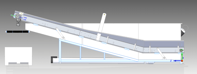
I don't think you have static equilibrium. At rest I think you do, 'cause I think there's other structure that the ramp is resting on.
I think the two links are parallel, yes or no ?
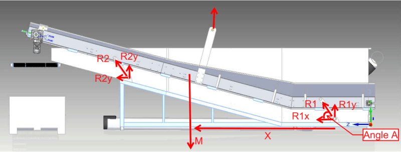
The two links are axial members.
The ramp when force F is applied will move (upwards and laterally) as the links rotate;
Until the links are aligned with the force F direction.
Now we have a geometry we can solve statically, and simply (like a SS beam).

Oh, I forgot about the weight.
Now the ramp becomes a three force body.
The forces in the links will have a common direction (parallel), so can be considered one force vector.
The weight is known (dividing between the two sides is reasonable).
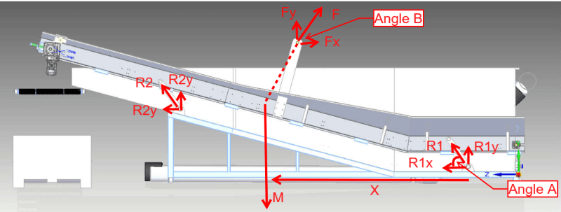
The applied force, F, is known, well is determined from geometry, but it's direction is known.
Then these three forces make a triangle. You know the three direction, so you can draw a triangle. You know one side, weight, so you know the other two magnitudes.
The remaining thing is to sort out the link loads, moments about one link attach pt would tell you the other link load, and so you'd have both.

And then solve for different positions, as the ramp is lifted and the links rotate.

another day in paradise, or is paradise one day closer ?
 
Hi roshane87

I don't believe you can assume that the chain angle which lifts the whole thing can be assumed to be Angle B, to me that chain doing the lifting could be vertical or some other angle it will change angle as the thing is lifted, unless of course you know something we don't, if so what's your reasoning for assuming angle B is fixed? In your first diagram you posted the lifting force (the red arrow) is shown vertical.
If however the lifting force F was coincident with the C of G throughout the lift I would agree with your logic but I don't think you can assume that.


“Do not worry about your problems with mathematics, I assure you mine are far greater.” Albert Einstein
 
Hi desertfox,

Angle A and B will vary with the height it's lifted. However, I can measure Angle A (and corresponding angle B) when it's at the lowest height and do the same for the highest because I will be determining where the chain gets fixed to lift the conveyor up.

The Force F and C of G wouldn't always be exactly coincident but it would be near enough. The C of G itself will vary on the conveyor due to it being under water and depending on which part is under water while lifting, the C of G will move slightly.

If we assume F passes through the C of G do you think we can statically solve this for various angles of A and B?

RN
 
Hi roshane87

If you feel that the error between F and the CofG is small enough to ignore then you can solve it the way you are suggesting. I don’t know physically what the difference dimensionally is,so not sure how small the error is, however if you are lifting by a crane you earlier mentioned,I can’t see how you can control the angle or positioning of the chain. 😀

“Do not worry about your problems with mathematics, I assure you mine are far greater.” Albert Einstein
 
how will you orient force F to be near the CG ? Sure you can draw a line on a sketch, but how will you do this in the real world ?

another day in paradise, or is paradise one day closer ?
 
Status
Not open for further replies.
Back
Top