Eng-Tips is the largest engineering community on the Internet

Intelligent Work Forums for Engineering Professionals

Lighting mounted on a pole in Catia FEM

Status
Not open for further replies.

reutov_tv

Industrial
Jan 16, 2024
33
0
0
US
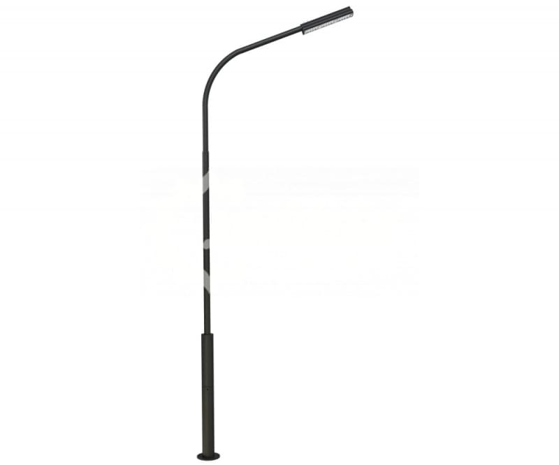
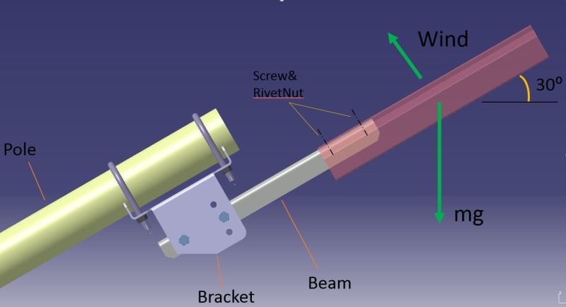
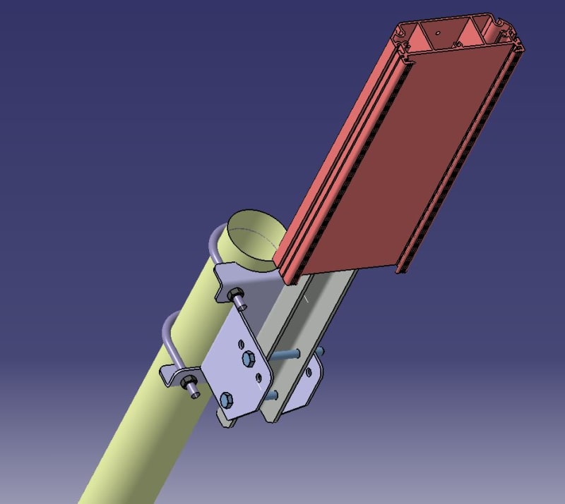
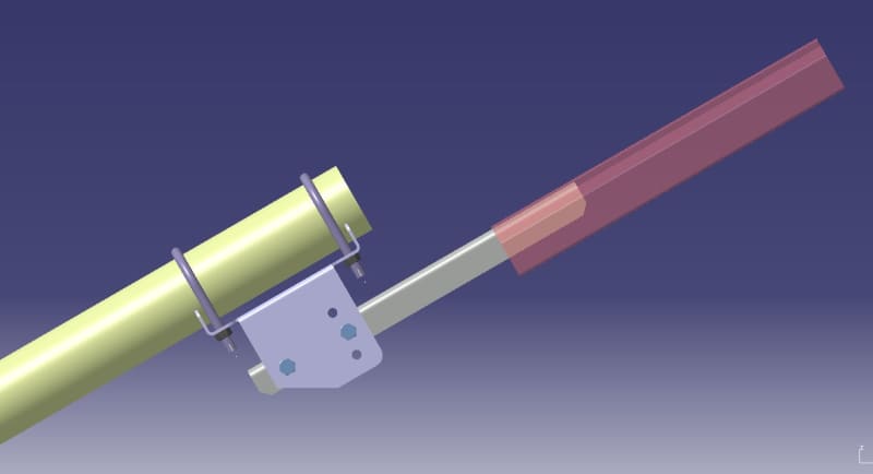
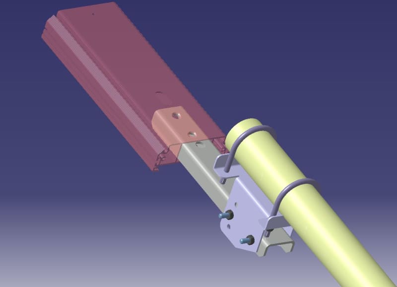
There is a lighting unit mounted on a streetlight pole using a beam and bracket.

Please advise how to make a rough static calculation before testing.
At the moment I believe the strength of the structure is excessive. (sheet metal thickness: bracket - 3mm, beam - 3mm). I would like to evaluate if it would be possible to use 2mm sheet metal.
Material - steel.


I have Catia build-in linear FEA tools only. Please recommend how to set up calculation scheme for this design.
Please take a look if it is correct to set the following?
1. U-bolts - rotation around pole axis only.
2. Bracket vs Pole contact area - rotation around pole axis for each flange.

Thread connections - could you recommend correct approximation method?

Respectfully,
reutov-tv

4_c7cub5.jpg
2_jw4si2.jpg
3_gyvkvc.jpg
1_atwlyv.jpg
 
Replies continue below

Recommended for you

What is the pole connected to? Is it a cantilever? What keeps the U-bars from slipping on the pole? Why not just use a rectangular tube and weld the attachment to that, or weld plates to the attachment/pole and bolt them (with slotted holes if one must be able to adjust the position of the "beam" along the pole)? The bracket looks unnecessarily complicated at first glance.

Bolts, plates and welds can be designed with hand-calculations. Calculate line loads for the parts, apply them (along and perpendicular to the axis of the beams), figure out shear and moment, calculate section properties, calculate bending and shear stress, calculate von Mises equivalent stress and check capacity. Compare weld strength to resultant forces at appropriate sections. No need for FEA.
 
Agreed, FEA is gross overkill for this. Make simple free body diagrams of the loads on each part, then simple hand calcs for strength and buckling for each part.
 
how big is this thing ? (no scale)

can you delete the grey piece, and have the light green piece attach directly to the U-clamps ?

as others, a simple structure, doesn't need FEA or complicated loads ... apply a conservative load (1000 lbs ?) in 3 orthogonal directions, that should kill it dead. How does the pole handle these loads ? What was the pole designed for ? something similar ??

"Hoffen wir mal, dass alles gut geht !"
General Paulus, Nov 1942, outside Stalingrad after the launch of Operation Uranus.
 
Thank you for your answers.

1. Pole like typical street lighting pole. (see photo below)
2. ME requirements - no welding, and U-beam should be used.
3. I am not Stress engineer, just ordinary designer.
4. I realize that Finite element is not easy. I understand that it takes years of practice in FEA and that there should be fresh (or strong) basics (at least in Strength of materials).


rb1957,
Beam section - 22mm*40mm. L=200mm..400mm (depends on the lighting unit dimensions).
No, it should be adjustable. (+/- 20*)
np5bb56kk4xudx1w7i2wsvqr92k712mz_fjubpq.jpg

 
So you're replicating this nice looking picture, by slapping a light on the end of an arm ? IMHO, it does look pretty ugly, but I guess it does accomplish the goal. A fiberglass cover would look nicer, a socket fitting would look very tidy.

If the end of the arm is now open to the elements (and intended to be like your picture, closed) what to do about rain water ? Is the outside of the pole protected from corrosion ? Is the inside ??

If meant to be adjustable (using those extra holes), ok, but does it clear the U-bolt in the upper position ?

Still, not much need for FEA.

"Hoffen wir mal, dass alles gut geht !"
General Paulus, Nov 1942, outside Stalingrad after the launch of Operation Uranus.
 
Status
Not open for further replies.
Back
Top