oengineer
Structural
- Apr 25, 2011
- 731
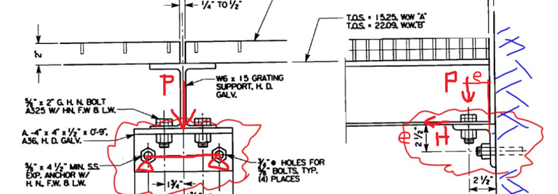
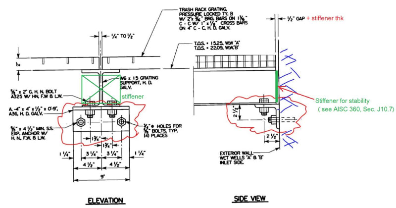
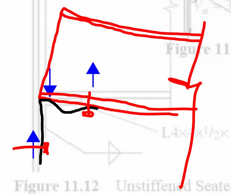
I am working on verify an angle connection that is being attached to a concrete wall in order to support a wide flange beam. The W-Beam is resting/beaning on top of the angle.
I have attached an example of the situation I have in the link ( the red clouded angle is the connection in question):
After checking the actual angle for moment stress, shear stress, and deflection I wanted to verify what the additional limit states that need to be satisfied for an angle connection.
Section J4 in the AISC Manual talks about limit states to be considered for connecting elements ( please see images below).
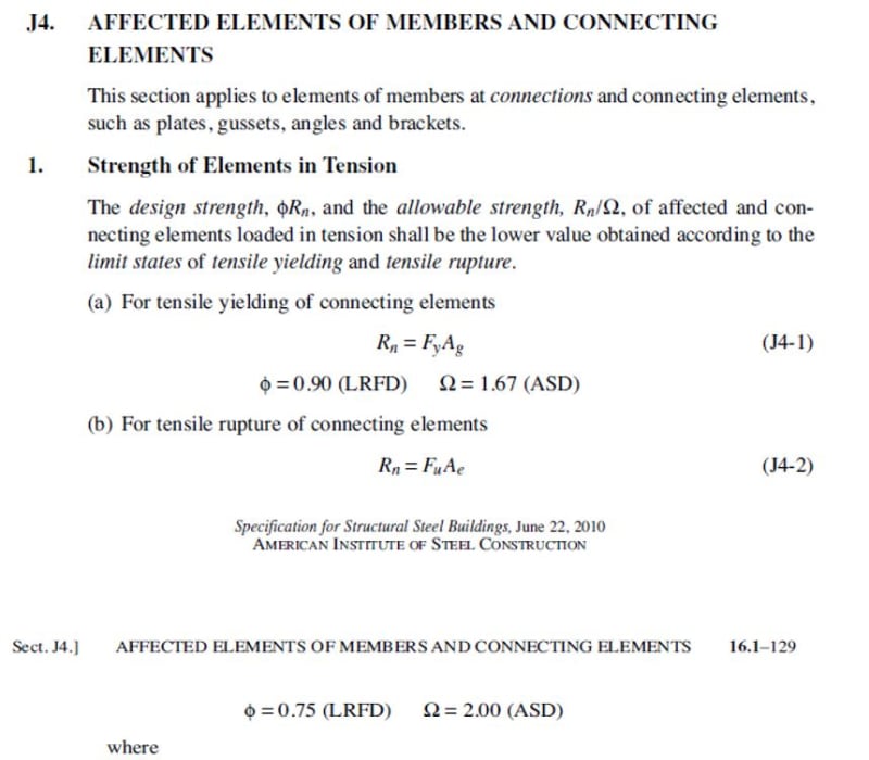
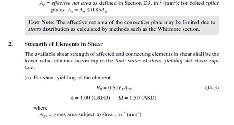
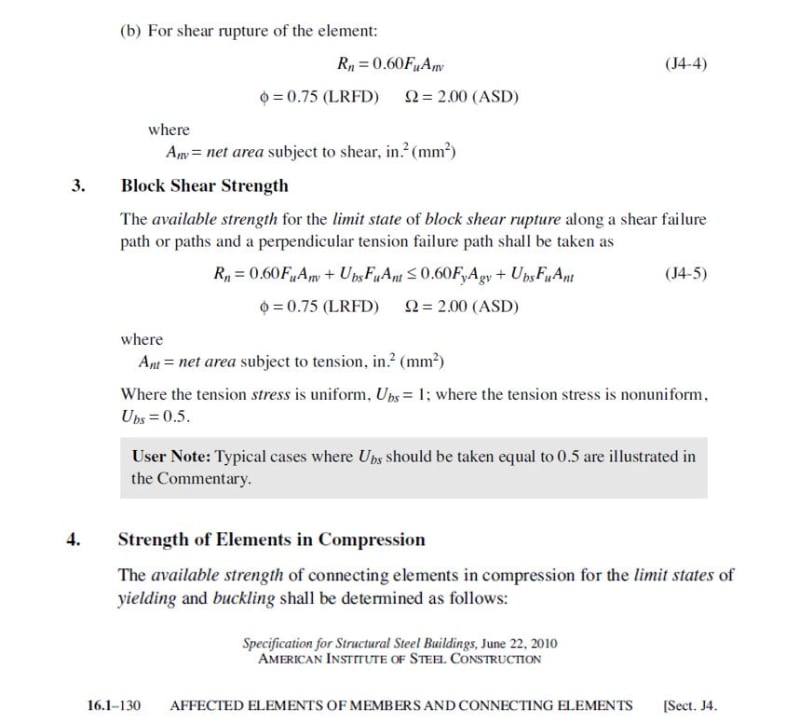
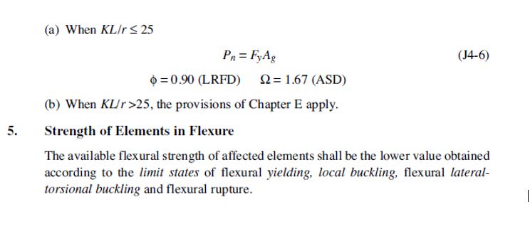
For the condition shown in the link, it appears that "Strength of Elements in Shear", "Strength of Elements in Compression", and "Block Shear Strength" need to be checked, per AISC Section J4. Please feel free to comment if there are any other special requirements for angle connections.
What about "flexural rupture" for the angle connection?
Would these be the only limit states that need to be satisfied or is there another section of the manual that I need to consider since the connecting member in questions is an angle?
Suggestions/comments are appreciated.
I have attached an example of the situation I have in the link ( the red clouded angle is the connection in question):
After checking the actual angle for moment stress, shear stress, and deflection I wanted to verify what the additional limit states that need to be satisfied for an angle connection.
Section J4 in the AISC Manual talks about limit states to be considered for connecting elements ( please see images below).
For the condition shown in the link, it appears that "Strength of Elements in Shear", "Strength of Elements in Compression", and "Block Shear Strength" need to be checked, per AISC Section J4. Please feel free to comment if there are any other special requirements for angle connections.
What about "flexural rupture" for the angle connection?
Would these be the only limit states that need to be satisfied or is there another section of the manual that I need to consider since the connecting member in questions is an angle?
Suggestions/comments are appreciated.