Continue to Site

Eng-Tips is the largest engineering community on the Internet

Intelligent Work Forums for Engineering Professionals

  • Congratulations cowski on being selected by the Eng-Tips community for having the most helpful posts in the forums last week. Way to Go!

Limit state checks for a steel angle bearing connection design 1

Status
Not open for further replies.

oengineer

Structural
Apr 25, 2011
731
I am working on verify an angle connection that is being attached to a concrete wall in order to support a wide flange beam. The W-Beam is resting/beaning on top of the angle.

I have attached an example of the situation I have in the link ( the red clouded angle is the connection in question):
After checking the actual angle for moment stress, shear stress, and deflection I wanted to verify what the additional limit states that need to be satisfied for an angle connection.

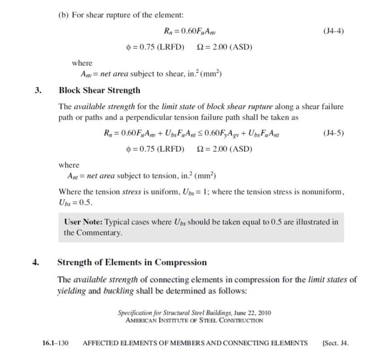
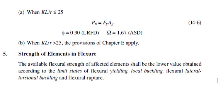
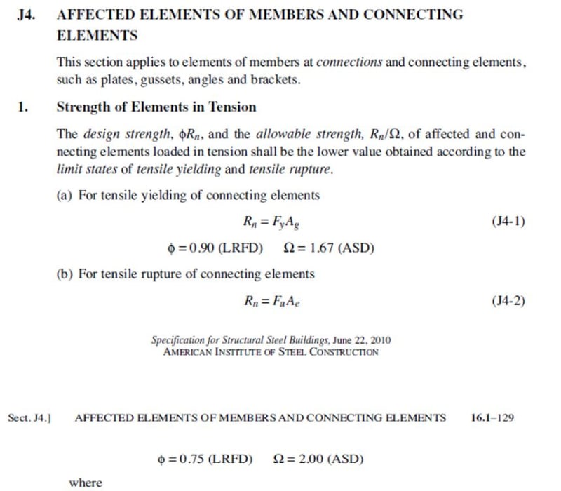
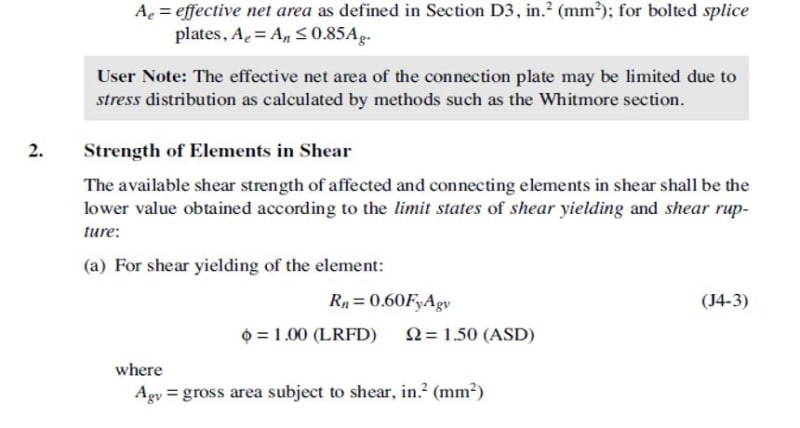
Section J4 in the AISC Manual talks about limit states to be considered for connecting elements ( please see images below).
connec1_orytfo.jpg

connec2_e2ffuo.jpg

connec3_pno6af.jpg

connec4_wnp5qz.jpg


For the condition shown in the link, it appears that "Strength of Elements in Shear", "Strength of Elements in Compression", and "Block Shear Strength" need to be checked, per AISC Section J4. Please feel free to comment if there are any other special requirements for angle connections.

What about "flexural rupture" for the angle connection?

Would these be the only limit states that need to be satisfied or is there another section of the manual that I need to consider since the connecting member in questions is an angle?

Suggestions/comments are appreciated.


Replies continue below

Recommended for you

PROYECTOR said:
Attached is a quite straightforward and reasonably conservative design model for unstiffened seated connections. The design values in the AISC Manual Table 10-5 are based on this design model.

This design example is for a welded seat angle, but the design model is the same for bolted seated connections.

Reference: Unified Design of Steel Structures, 3rd Ed.

The example is quite helpful but I would just like to confirm how to proceed when negative " N min" values are obtained.
 
oengineer,

Can you provide the equation for determine the bearing dimension "N"? IMO, unless the load is uplift, N shall always > 0.
 
retired13 said:
oengineer,

Can you provide the equation for determine the bearing dimension "N"? IMO, unless the load is uplift, N shall always > 0.

Ru = 13.34 kips, a W8x35 (Fy = 50 ksi) and a L5x5x7/8" (Fy = 36 ksi).

Using the equations Nmin = Rn/(Fy*tw) - 2.5k, I get a "Nmin" equal to -1.362 inches. This is for Determining the minimum required bearing length for web yielding.

For Determining the minimum required bearing length for web crippling, assuming that N/d < 0.2, I use the equation Nmin = d/3[Rn/(0.40(tw)2)((tw/EFytf)^(1/2)-1]x(tf/tw)^1.5 and yielded a value of -3.801 inches.

These equations are the same ones used in the example problem.

Even the example problem yields a negative value for the Determining the minimum required bearing length for web crippling, assuming that N/d < 0.2 check. But the difference is that the absolute value is less than the Kdet of the beam.
 
oengineer said:
The example is quite helpful but I would just like to confirm how to proceed when negative " N min" values are obtained.

The answer to your question is in the book:

Unified Design of Steel Structures said:
Because the unstiffened angle is a very flexible connection, the load levels usually considered are quite low. This tends to result in very small minimum required bearing lengths and, in some calculations, a negative minimum required bearing length. To offset this potential problem, the minimum bearing length for seated connections is taken as kdet.

In short, if N min is negative, then you should use N min = kdet


PROYECTOR said:
The answer to your question is in the book:

Quote (Unified Design of Steel Structures, 3rd Ed. p. 518)
Because the unstiffened angle is a very flexible connection, the load levels usually considered are quite low. This tends to result in very small minimum required bearing lengths and, in some calculations, a negative minimum required bearing length. To offset this potential problem, the minimum bearing length for seated connections is taken as kdet.

In short, if N min is negative, then you should use N min = kdet

This is what I was thinking, but I wanted to verify. Thank you!
 
Ok, when you get negative N, it indicates the web of the wide flange is stiff enough without the problem under checking. (Note, the N in AISC equation is a given dimension as indicated in PROYECTOR provided graph case (a) or (b). It is then used to calculate the nominal strength of the web of the wide flange to resist web yielding and web crippling. The reverse calculation of N has no physical meanings.)
 
Status
Not open for further replies.

Part and Inventory Search

Sponsor