Eng-Tips is the largest engineering community on the Internet

Intelligent Work Forums for Engineering Professionals

  • Congratulations waross on being selected by the Tek-Tips community for having the most helpful posts in the forums last week. Way to Go!

Line-Earth Voltage in 3Phase unbalance loads 6

Status
Not open for further replies.

MAZ13

Electrical
Apr 21, 2011
15
0
0
DE
Hi all,

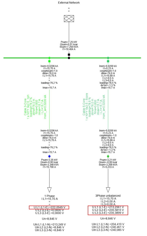
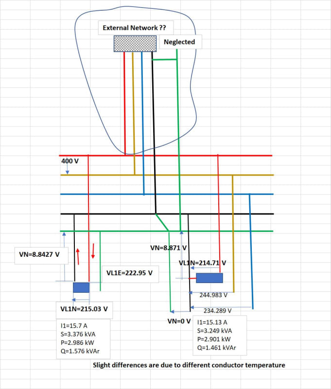
If we have a 3phase unbalance load (400V L-L, 230V L-N nominal voltages), which all loads are on 1phase and the other phases are unloaded, is it expected that L-E voltage in unloaded phases changes? (anything rather than 230V?)

I know that by unbalance loading, neutral point displaces and neutral voltage is something rather than 0. Therefore I expect L-N voltage changes on all phases. But my question is about line to earth voltage.
I ask this question because software simulation of such unbalanced load by DIgSILENT power factory shows such strange results!
 
Replies continue below

Recommended for you

MAZ13 said:
...However, DIgSILENT shows change in Vb and Vc! and important point: this is because of cable. It means when I use a 3core cable, the results are so that I expect, but when I use 5 core cable, these strage results come out.

The best way to give you a proper answer regarding this last issue would be if you post the circuit you are simulating and where are you measuring the voltages to ground on DigSilent, at least a handmade rough diagram with both cases: 3 core cable and 5 core cable.

Or we will continue to guess what's going on.
 
argotier:
For the neutral grounded at the source;
In your diagram, the neutral displacement will be along the line A-E, from E towards A.
Yes, the voltages to ground on the unloaded phases will be unchanged but the voltages on the unloaded phases from line to neutral, taken at the point of the load will change.
If you modify your sketch so that the neutral displacement is on the line E-A, then the voltages and the voltage changes from line to neutral compared to line to ground (E) will be clearly shown.
MAZ13;
Three phases and a neutral requires four wires.
I am wondering about the connections of the 3 core cable and the 5 core cable.
What are your strange results?

Bill
--------------------
"Why not the best?"
Jimmy Carter
 
Hi all,

Please see attached pic.
I have simulated 2 cases: on the left side is a single phase load 15,7A, supplied from phase L1.
On the right side is a 3phase unbalanced load, which all load (15,7A) is on phase L1.

Supply cable cross section is same 2.5mm2 in both cases.

I expect no difference between these 2 cases. It means: I expect same L1-E voltage, same neutral voltage (as it is) and same L1-N voltage. Also I expect L2-E and L3-E stay 230V (nominal voltage) because they are unloaded (while L2-N and L3-N could be different because of neutral displacement).

I don't know why the results on 3phase load do not follow my expectations! Do you have any Idea?

 
 https://files.engineering.com/getfile.aspx?folder=ab7d6891-e954-45cd-a305-d696fe7f4709&file=Bild.jpg
Try running a simulation with a unity power factor load.
Your non-unity power factor load is skewing the neutral offset.
It is the skewed neutral offset that is cauaing the unequal phase voltages.

Bill
--------------------
"Why not the best?"
Jimmy Carter
 
Here are my comments on your attached diagram:
Source: it could be a transformer and one need to know Srated , uk% and load losses in order to calculate Zxfr and the actually voltage drop.
Whatever the busbar potential has to be 225 V [390 V between phases].
3*2.5 mm^2 side:
It seems you have a neutral conductor still, other way I1=Io=0 since no other return way.
5*2.5 mm^2 side:
It seems to me that it is correct [ and 60oC conductor temperature it is o.k.]
 
Dear Waross

This is the case with unity power factor. There is not too much differenece:
PF_1_owpmsd.jpg
 
Dear 7anoter4

What are you talking about? The network is as simple as is indicated. There is no transformeres and for voltage drop calculations you don't need to know what equipment is on upstream! Voltage on main busbar is 400V-3ph-N.

Left side is a single phase load (L1-N) which is supplied from 3x2.5mm2 cable.
On the right side is a 3phase load (Y-N) supplied from 5x2.5mm2, that just phase1 is in service. It means that actually a single phase is in service and there should be no difference between the results on right and left side. At least I think so!
 
With a unity PF load, the L2 and L3 voltages should become equal, removing some of the strange effects originally shown.
The hand calculation of both the single phase line to ground voltage and the single phase line to neutral voltages becomes more straightforward.

Bill
--------------------
"Why not the best?"
Jimmy Carter
 
I don't like a program made by others for sale because you don't know exactly what kind of data the robot wants to be given and how to interpret exactly the data that the robot provides you.
In this case, which is extremely simple - a simple calculation with a single-phase voltage - it has become enormously complicated with a three-phase network and a lot of unnecessary data.
I think that using a three-conductor cable in a three-phase network, the robot considered three phases. So, I consider that you only have a two-conductor cable to employ.
 
Could anyone simulate this example in any other software and share the results? So we may compare the results and get to a conclusion.
 
I'm kind of old school.
Rather than play musical software, we dinosaurs would hand calculate the answer.
I had a hard day today and am too tired to take that on just now.
Maybe someone else will.
I don't think that the software properly understands the question and I don't think that we properly understand what the software is trying to tell us.


Bill
--------------------
"Why not the best?"
Jimmy Carter
 
From the attached diagram that was made by the computer, it is difficult to understand what each digit represents.
For example, the diagram shows an External Network and next to it a current and three-phase active and reactive power values. It is not understood whether they represent nominal values or a certain load.
Also for the 5 * 2.5 cable, 2 currents are noted, one in three-phase and another in single-phase.
In order to calculate the voltages towards the neutral and towards the earth, a real scheme is needed.
I think there are actually two different overlapping problems, one three-phase and one single-phase.

 
 https://files.engineering.com/getfile.aspx?folder=25e67d7c-0e6c-4137-bcaa-174f9fcf517f&file=External_Network.jpg
Do you have a model that we can look at or can't you be bothered providing that kind of info? I'm completely dumbfounded that others here are trying hard to figure this out without even seeing a model of the system you are posting about.
 
Hi all,

sorry for late answer.

I'm surprised what special data are you looking for?
The short circuit capacity of "External Network" , as an input data for example, has no role on voltage drop calculation! Main busbar should be considered as "PV" and External network produces as much power as required to maintain 1pu voltage on main busbar (there is no other meaningful option! How else could one simulate this?)

There is no cable between "External Network" and main busbar. Therefore there could be no more this question, if the Neutral is earthed on External Network or on main busbar!

My input data about cable is cross section (2.5 mm2) and length (76 m). Load current is 15.7A with 0,92 capacitive power factor.
Any other parametere should be calculated.

Please clear it up, what parameter or model data are you looking for.
 
Dear 7anoter4

you made it well. Thank you.

Now the question is about "VL1E" , "VL2E" and "VL3E" in your 3phase load. Could you indicate it on the diagram?

By me, "V1LE" , "V2LE" and "V3LE" are far away from my expectations and it made me to raise this thread.
 
Status
Not open for further replies.
Back
Top