Eng-Tips is the largest engineering community on the Internet

Intelligent Work Forums for Engineering Professionals

Line Profile of Bent Bar to be inspected with Envelope Gauge

Status
Not open for further replies.

TopPocket

Mechanical
Feb 16, 2022
50
0
0
GB
Hi, I'm an ISO guy.

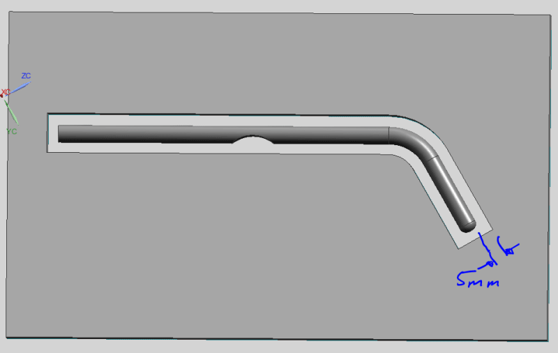
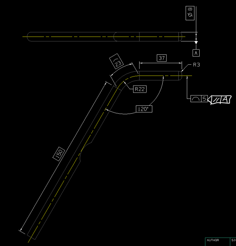
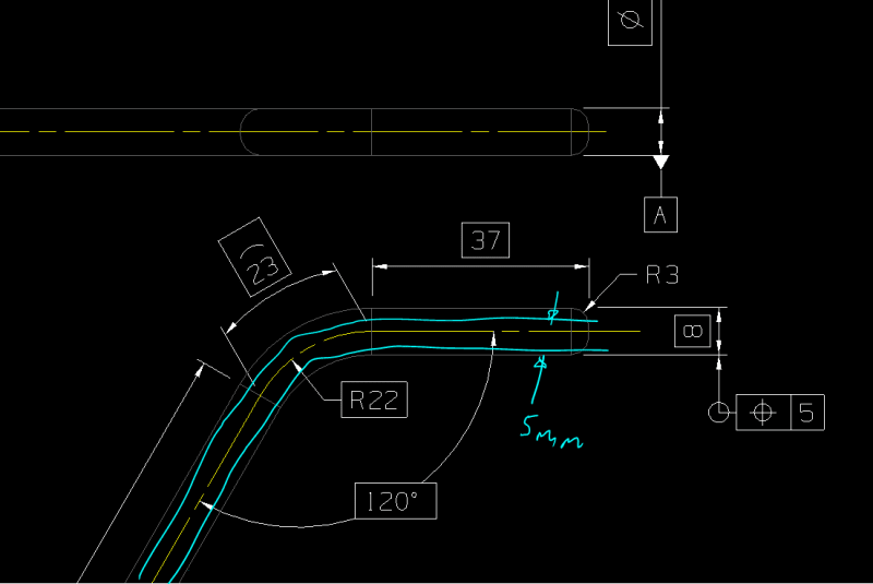
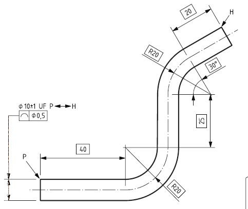
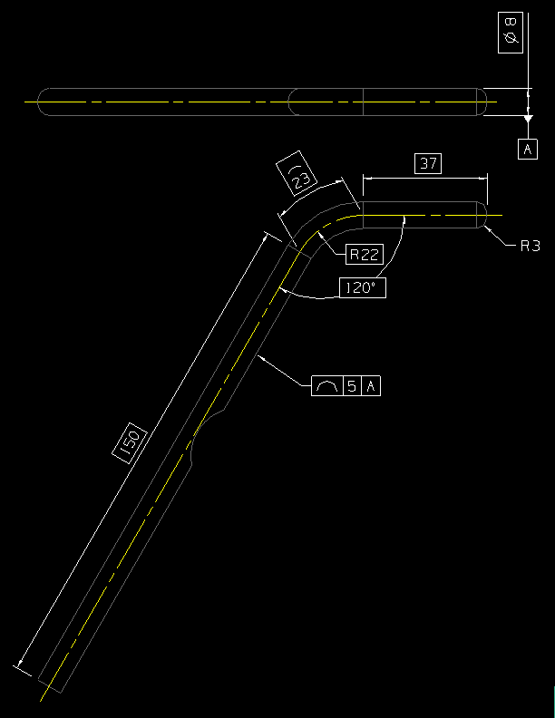
So I have a part which is basically an Ø8 mm bar bent into an "S" shape.
All the bends are in the same plane so it should lie flat on its side.
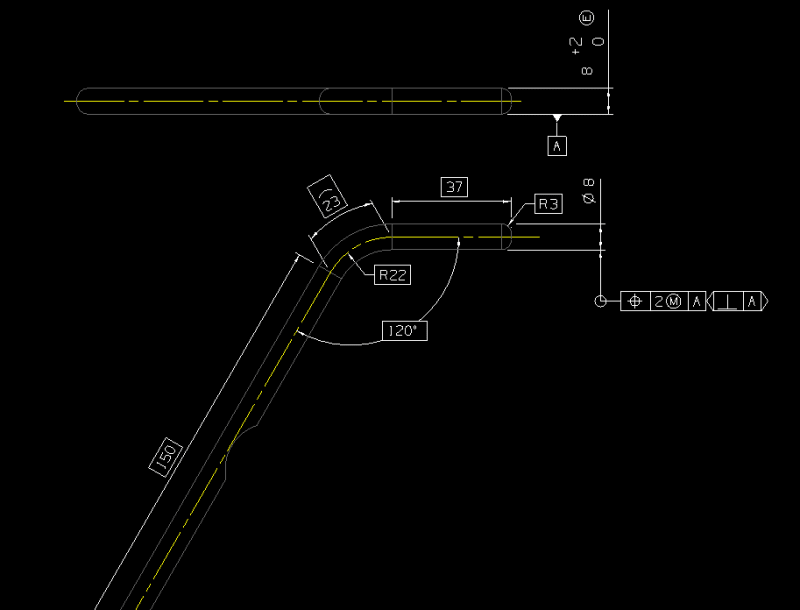
To inspect it I'm going to create and envelope gauge to put it in.

So to link the part with the gauge I'm going to define the axis of the bar with TEDs and apply a geometric constraint to the surface. The same axis can then be used to define the envelope gauge, but just bigger but my tolerance.

I think that's quite a clean connection between part and gauge and does everything I want without extra angle measurements etc.

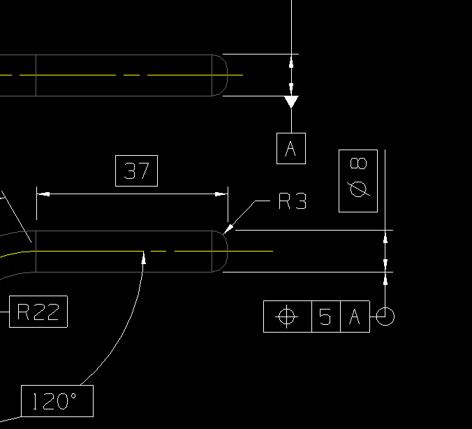
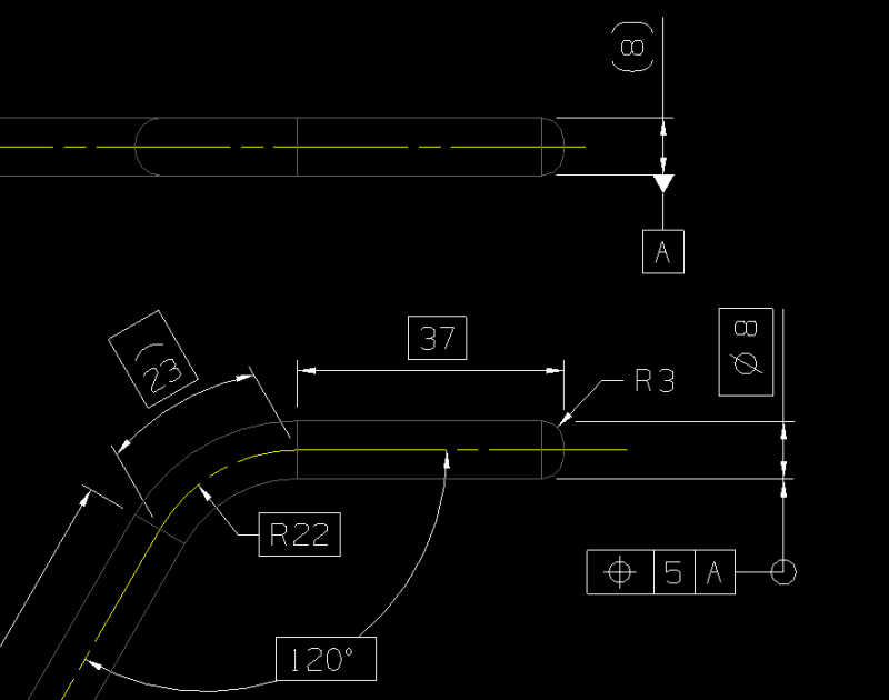
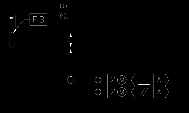
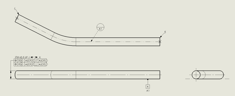
Now, simply I'm defining datum A as the plane that cuts through the axis of all the bar, so the midplane of the part. First question is am I defining this correctly on the drawing?

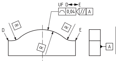
Then to define the tolerance I'm applying a line profile tolerance to the outside of the part. Do I define this to A or do I use and orientation plane to relate it to A? I want to essentially say check the line on the midplane of the part (which should be the theoretically largest cross-section) fits within a boundary defined by the TEDs.

At the moment I've got a note just basically saying that for the 99% of people who haven't digested ISO 1101 (myself included if I'm honest).
 
Replies continue below

Recommended for you

OP said:
I'm going to define the axis of the bar with TEDs and apply a geometric constraint to the surface.

OP said:
Now, simply I'm defining datum A as the plane that cuts through the axis of all the bar

Does the Ø8mm bar bent have a ± tolerance OR Ø8mm it is TED?
If you apply a datumless profile to the outher boundary of the "S" shape why this wouldn't be enough?
I mean Ø8 being TED and profile |xxx| for the OD of the bar.
Now, UF or CZ might be needed but the gist is there.....
Again, I am asking....not sure my solution is correct or not....


jassco said:
Are you going to use a CMM or a hard gage to inspect this part?

I'm going to use a gauge, a pocket defined by the TEDs and line profile tolerance. So for our Ø8 mm bar with say a 5 mm profile tolerance we'd basically have a 18 mm wide slot with the same centerline.

I've popped a simplified version below which will hopefully answer some questions:
defining_bendy_lcquk9.png


So hopefully that way of defining datum plane A makes sense.

And I've put the line profile tolerance with just the datum reference in the frame. Is this enough? Or should I use an orientation plane?

Also there's some features that aren't TED that I don't want to be included in the envelope, such as the rad and the cut out. If I include a note saying the part is to fit in an envelope defined by the TEDs is that enough to cover it do you think?

Thanks :)
 
Hi, TopPocket:

I have not used ISO standards for decades. So, I am no longer familiar it.

In ASME Y14.5, I would use flatness of "derived medium plane". You just add a flatness to thickness of the part. You will need to make two gages within a narrow window (height: 3mm and 13mm not 18mm). The gage with opening of 3mm is a No-Go gage, while the one with opening of 13mm is a Go gage.

Best regards,

Alex
 
Hi Jassco, ISO is a bit of a pain due to how dense the language is and lack of clear examples.

You've misinterpreted the intention of the drawing which means it's probably not correct. At least we're learning.

I think the problem is the orientation I want the profile of a line to control is unclear, which is why I think using a orientation plane indicator is the way to go, making it parallel to A.

One problem I've found is I have no idea how to create this symbol in NX.

Here's a picture of what the gauge would look like. So really it's only a Go Gauge, the NoGo aspect of the profile of a line tolerance would be a part with negative 2 diameter, which hopefully is nonsensical enough to not be taken as the intent.
bendy_gauge_slot_uwsxnq.png
 
jassco said:
In ASME Y14.5, default profile of a line is symmetric. Does ISO 1101 have a different definition?

I think it's the same, it's basically straightness applied to a non flat surface right. But in my case I don't actually care about one side.

I see what you mean about it being 13mm not 18mm now as it describes the tolerance width. Maybe there's a better way to define this...
 
Hi, TopPocket:

In ASME Y14.5, there is something called "Bidirectional Positional Tolerancing (Rectangular Coordinate Method)". You can apply positions to control axis of your part on datum A. I am not sure if it works in ISO. If you have a copy of ASME Y14.5-2018, please see Figure 10-29 on page 205.

Best regards,
Alex
 
Hi jassco,

The only ASME I've got is GeoTol Pro but I can seem to find any reference to bidirectional positional tolerancing.

This is what I think I need to do in the ISO:
iso_1101_eg_qtfygv.png


I don't think I really want to control orientation, just the form.

Could I do it by controlling the axis instead like so?
is_this_is._dlyjwu.png
 
Hi, TopPocket:

I don't think ISO allows to attach a FCF (feature control frame) to an axis. If I were you, I would add width dimension (8mm, no diameter symbol) and attach a position tolerance (without a diameter symbol again) to this width dimension.

You may find the attached image useful.

Best regards,

Alex

Figure_10-35_Positional_Tolerancing_Boundary_Concept_ASME_Y14.5-2018_xxbzeq.jpg
 
Do you notice that both dimensions 7 and 14 do not have diameter symbol? Also, do you notice that position tolerances 0.25 with a cycled M and 1.5 with a cycled M do not have diameter symbols?
 
So perhaps this then?
ggg_hfgz4n.png


So to me this is implying the axis of the bar is to be confined by the blue tolerance planes shown.

Not having the diameter symbols on the position tolerance makes sense, but I don't see what's wrong with having it on the 8.

Couldn't you also tie it to Datum A like so?
effff_thax7w.png


The position tolerance still implies two planes (curvey planes, if you know what I mean), perpendicular to A, which the axis of the bar must reside in.

I guess the nice thing about it being to the axis/midplane is it makes the tolerance only have a one boundary. Though the gauge would interact with the surface so might need some additional interpretation...

In regards to your other comment:
I'm not sure why you would put diameter symbols on any of those tolerances as they are for slots, so have a median plane not an axis.
 
Well, if you attach both datum A and the position FCF to dimension Dia. 8, then it is like a dog chases its own tail.

Best regards,

Alex
 
yeah I see what you mean, and I actually cropped out the top one by mistake which I had set to (8), so a reference, none diameter, to help try and distinguish the datum plane, and the bent axis of the part to which the position applies. see what I mean below:

fefef_kv2vlh.png


Is the a symbol I could apply to the lower Ø8 that would imply it applies all along the length of the bendy part?
 
Okay,

So I've got this now, which I admit, find a bit disgusting, but I do think it's accurately describing the situation:
monst_uooik5.png


So the top 8 +2 (E) dimension is there to check the bends are done in the same plane (for a part with 2+ bends). Could be easily checked by placing a parallel on a couple 10 mm gauge blocks on a granite table and sliding the part through the resulting 10 mm slot.

I've moved datum A to the underside rather than the mid plane to make it more tangible.

I've made the dimensions on the axis all TEDs to define the nominal axis of the part which is controlled with the position constraint. As aforementioned the nice thing about position on an axis is it is essentially single sided, so unlike a surface profile, we don't have to worry about the LSL so to speak.

The Ø8 is not a TED as I've put MMR on the position. the MMR links the axis to the surface which allows me to inspect the MMVC (the boundary). Position is constrained by datum A, I'm not 100% I need this to be honest, especially with the orientation plane.

I managed to create my own symbol so I could add the orientation plane indicator. This is saying that the two planes defining the tolerance zone must be perpendicular to datum A. So I don't care about any up or down (that's controlled by the 8 +2) or any diagonal mess.

The all around symbol indicates it's for the whole axis, I think this is the best way to indicate that...


Anyway, what do you think?
Is it a monster?
Is anyone actually going to understand it?
Why even use GD&T if noone gets it?
 
Now I think I'm getting a grasp of orientation planes, I guess the top 8 +2 (E) dimensions could also be described with position, but just with a parallel orientation plane. (slight change to the tolerance due the the MMR but this can be modified with the pos tol)

WEFFF_fzgama.png

so this is identical:
qqqq_iz4imu.png


Only thing is the MMR still feels like a bodge to get around the bilateral nature of tolerances.

Would be nice to have it as a surface profile with something that says "USL only".
 
A bit late but this problem got me thinking. I think your final suggestion is reasonable given the constraints you've laid out, although I've got a couple of comments:
[ul]
[li]application of all-round should instead be changed to the between symbol with the start and end of the rod defined such as the example below from ISO 1660.
Capture_mrakev.png
[/li]
[li]It may provide some clarity to define datum A as a planar contacting feature since this is how you want to inspect it.[/li]
[li]If implementing the above, Datum A should be included in the position FCF since it constrains the orientation of the tolerance zone.[/li]
[li]The diameter of the rod should have a tolerance and should probably be defined as a united feature.[/li]
[li]The application of orientation plane here is undefined in the standard, but I think it's not too much of a stretch to figure out the intent.[/li]
[/ul]

Here's my suggested drawing which implements these suggestions, excluding any TEDs.
Capture_cczmvu.png


Ryan.
 
Status
Not open for further replies.
Back
Top