TopPocket
Mechanical
- Feb 16, 2022
- 50
Hi, I'm an ISO guy.
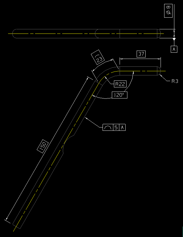
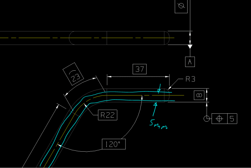
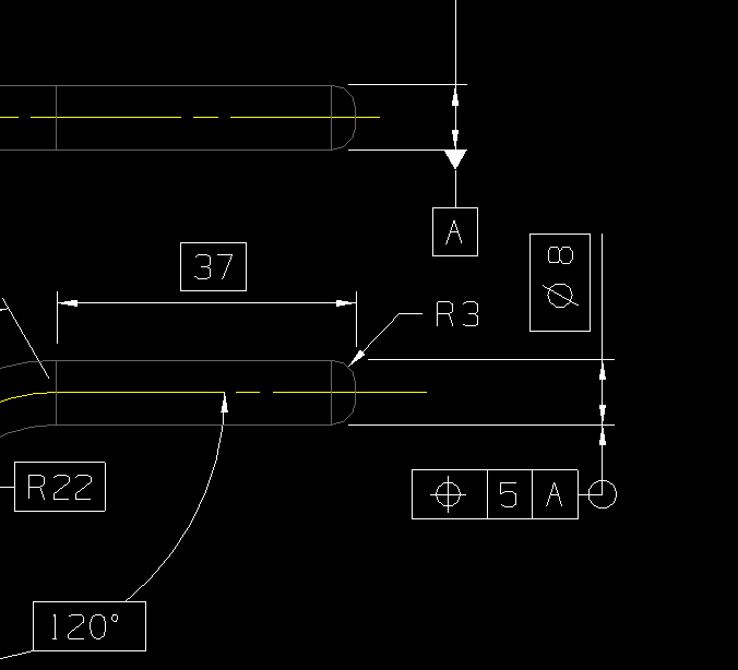
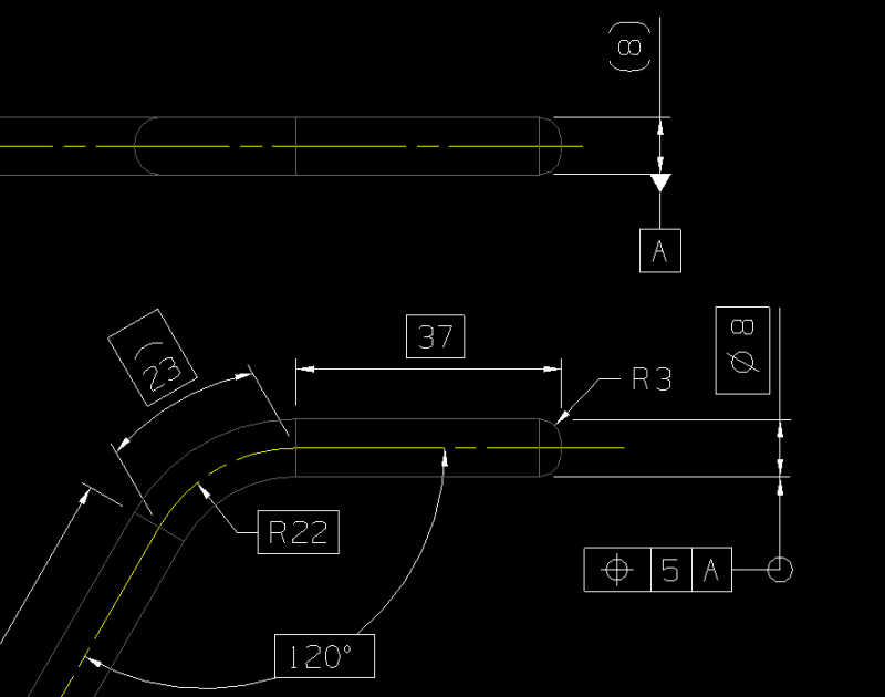
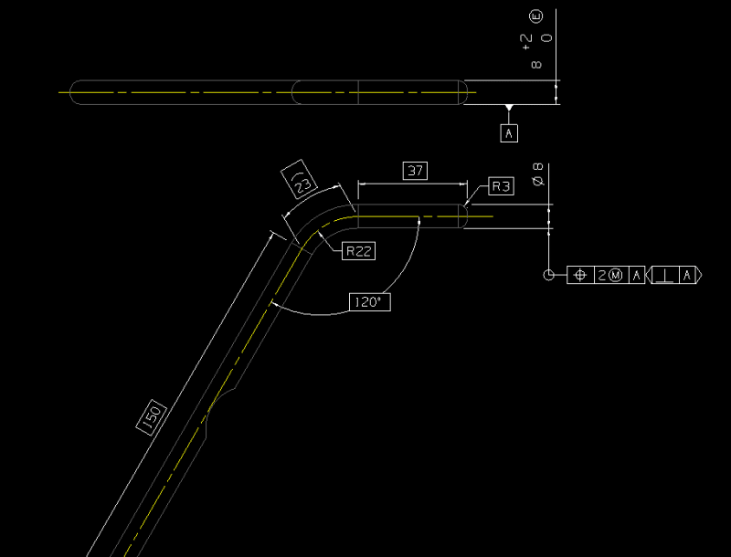
So I have a part which is basically an Ø8 mm bar bent into an "S" shape.
All the bends are in the same plane so it should lie flat on its side.
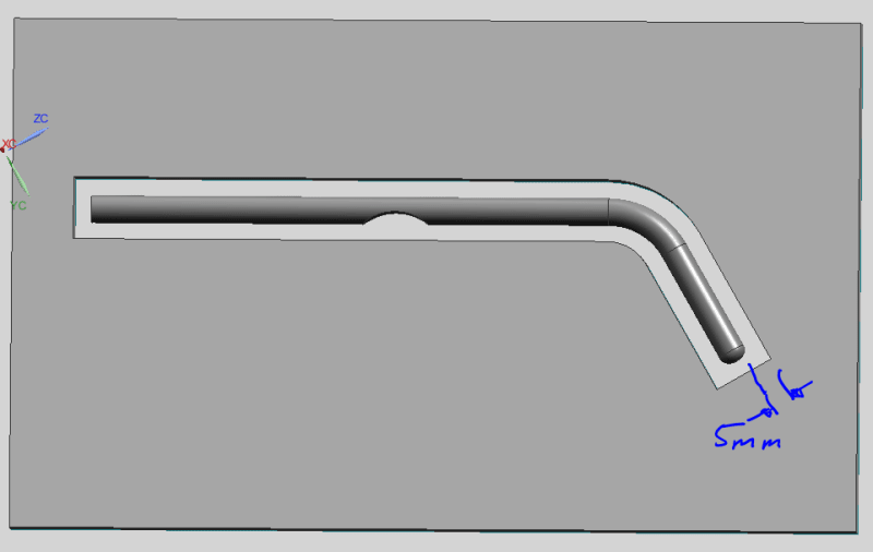
To inspect it I'm going to create and envelope gauge to put it in.
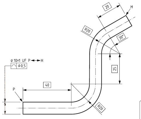
So to link the part with the gauge I'm going to define the axis of the bar with TEDs and apply a geometric constraint to the surface. The same axis can then be used to define the envelope gauge, but just bigger but my tolerance.
I think that's quite a clean connection between part and gauge and does everything I want without extra angle measurements etc.
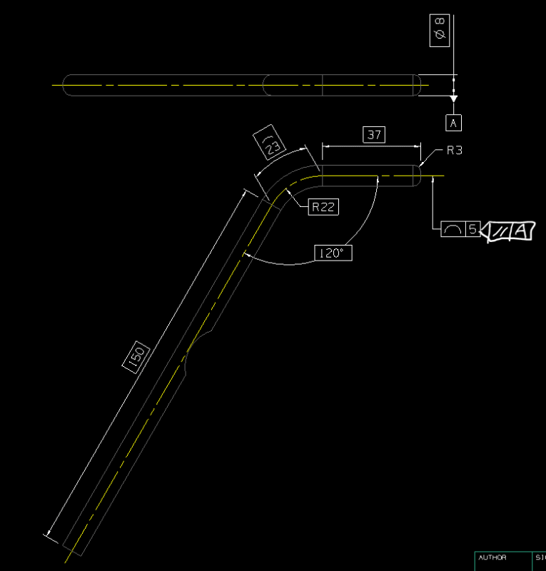
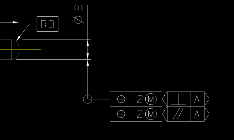
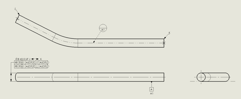
Now, simply I'm defining datum A as the plane that cuts through the axis of all the bar, so the midplane of the part. First question is am I defining this correctly on the drawing?
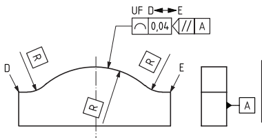
Then to define the tolerance I'm applying a line profile tolerance to the outside of the part. Do I define this to A or do I use and orientation plane to relate it to A? I want to essentially say check the line on the midplane of the part (which should be the theoretically largest cross-section) fits within a boundary defined by the TEDs.
At the moment I've got a note just basically saying that for the 99% of people who haven't digested ISO 1101 (myself included if I'm honest).

