Eng-Tips is the largest engineering community on the Internet

Intelligent Work Forums for Engineering Professionals

LMC

Status
Not open for further replies.
Replies continue below

Recommended for you

1.) Is this an ISO drawing or ASME?
2.) Regardless if ISO or ASME, I am not sure the drawing is correct. Why the position tolerance is on the dimension and not on the feature / slot?
I think 1.753 should be basic, the slot should be dimensioned for size and located with position (at LMC if desired)
3.) Looks like datum feature A is not very stable, or not able to stop degrees of freedom to get repeatable and reproducible measurements. Am I the only one thinking that maybe a secondary datum feature (or even tertiary) might be needed?


The design engineers response to our question was;

"As the slot becomes more oversize its location becomes less critical. At LMC The location can be off 0.010 more than at MMC."

The dimension 1.753+/-.003 is measuring 1.763.

Note:
We rarely ever see LMC used and when we do it's nearly always applied to a hole close to an edge and there are two datums.
 
ozzy1 said:
"As the slot becomes more oversize its location becomes less critical. At LMC The location can be off 0.010 more than at MMC."
That's fine, however, probably the "language" (read GD&T language) could be improved to reflect the design intent (your above English written verbiage). I don't think what the drawing says NOW is in agreement with your above quote from design engineers.

 
Ok, lets say we stay with what the language is would you say the 1.763 insp. result is acceptable? In addition could detail how you think the language should be.

Thanks
 
ozzy1 said:
As the slot becomes more oversize its location becomes less critical.

If this is the design intent then maybe MMC IS the correct application (and not LMC).
it is just me or your design engineers have it backwards....


ozzy1 said:
The dimension 1.753+/-.003 is measuring 1.763.

Measuring the slot size and measuring the slot LOCATION has almost nothing to do with each other.
They are related/ linked thru the usage of LMC (or MMC which I think it is the design intent), but that's about it.

By the way: again, is it ISO or ASME?

 
Engineer is a young guy. We usually work well together but when we (QC) question something like this the reaction is 'well what the hell do you know you are just QC'.
 
That's is fine by me.
Just tell the "young guy" that what he says on his print (regardless if he made the print or inherited like that--from an "old guy")) is NOT reflecting the design intent (English written explanation "The design engineers response to our question was;
"As the slot becomes more oversize its location becomes less critical. At LMC The location can be off 0.010 more than at MMC.").

ASME which version? ....just to establish the level of playing field


ozzy1,

Neither FCF shown (if the one with symmetry can even be considered an FCF - its certainly not formatted properly, missing datum references, etc.. and if its not meant to be an FCF I'm not sure what its trying to convey) is attached to an actual feature which is not allowed per ASME. Position must be attached to a physical feature, not centerlines/points/planes.

As the slot becomes more oversize its location becomes less critical. At LMC The location can be off 0.010 more than at MMC.
You have just described the behavior of an MMC control, not LMC. When position is controlled at MMC, the allowed deviation increases as the size departs from MMC towards LMC.

I also agree - datum feature A is itself probably insufficient to control all the desired DOF, as well as certainly doesn't control rotation so unless its held in simultaneous requirements to all the other features of this part (doubtful) additional datum references should be utilized to control the free DOF.

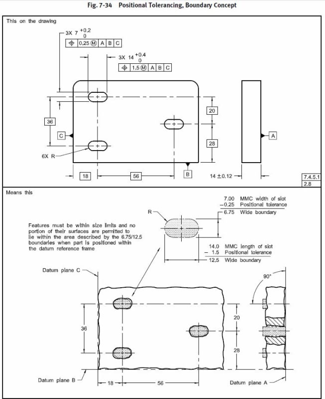
You said the engineer is a young guy - titles do not by themselves bestow knowledge. Perhaps a refresher GD&T course would be helpful, the way it is applied here shows some......room for improvement. Below is one of the recommended ways to control the position of a slot (note the FCF's applied to physical features and incorporation of basic dimensions to establish true position of the slot). That or profile would be viable options - but the way it is shown on the drawing you provided is not interpretable per ASME Y14.5

7-34_slot_mkz6f2.jpg
 
Version ASME Y14.5M-1994 is the standard generally used here. Let me digest and get back to you later.

Thanks much guys.
 
Status
Not open for further replies.
Back
Top