Continue to Site

Eng-Tips is the largest engineering community on the Internet

Intelligent Work Forums for Engineering Professionals

  • Congratulations KootK on being selected by the Eng-Tips community for having the most helpful posts in the forums last week. Way to Go!

Load Distribution on Precast Double Tee

Status
Not open for further replies.

JohnRwals

Structural
Jul 8, 2020
146
Hello!

Let's assume two single stem Tees (independent L1xW1 and L2xW2) are combined rigidly into one double tee
along the stitch line.
I wonder how a load will be distributed to each stem.
Do you think a load will be transferred according to the stiffness (k1, k2) of each stem?
Also, how can I find the maximum deflection points?
I guess the largest deflection points will be different from the midpoints, L1/2 and L2/2.
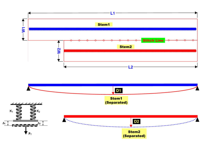
Double_Tee_Modeling-1_bkxcgy.jpg
 
Replies continue below

Recommended for you

No, I just selected the strands based on that chart. The sections are single tees as drawn.
 
Great stuff @Brad805 !

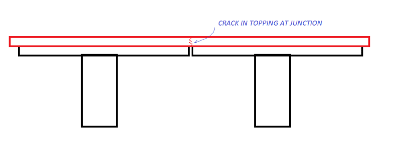
One thing I'd like to check with you - does your model account for reductions in shear stiffness once the topping fully cracks at the junction between the T beams ?
Capture_rheaog.png


If the junction gets through cracks (likely if it's very thin), the only load transfer mechanisms would be tension carried by steel and compression from the two Ts wanting to press up against each other (ignoring shear friction available to the concrete post cracking and any stiffness arising from rebar dowel actions). This might reduce the overall load transfer further between the two.
 
FE,

I don't think any analysis tool can consider these detailed variables.
Too abstract and advanced expectation beyond reality [idea]
 
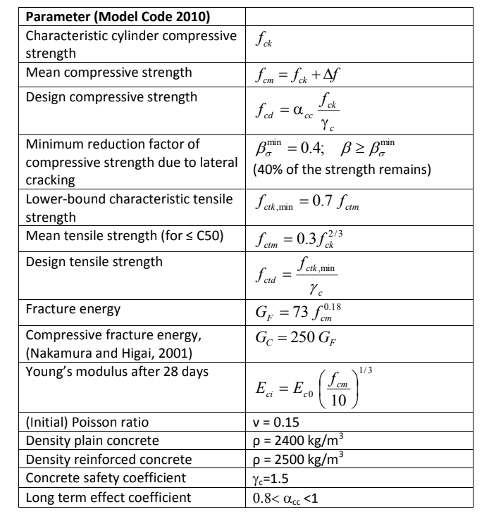
The material properties for the concrete are below. I may look at the other material models that might be more applicable in a case like this. The mesh size is likely another problem. These models can take some time, and one usually works out the kinks before refining the mesh size. This is also the point where I would reach out to the experts for advice.

model_code_tuhwb3.png


I did try adding an interface material between the topping and the tees. As expected that leads to convergence problems in the load steps. I tested two different options and neither work great, but there is notable tension between the topping and the tees. In addition to the shear, I think adhesion may play a role in the load share question. I tend to agree that this problem has a few too many variables, but I will pay more attention to a few details in the future as a result of the discussion.
 
I would like to ask practical questions.
So, how can I analyze this DOUBLE TEE case approximately/MANUALLY without using software assistance?
Can I calculate with two separate single tees with the same load condition, w1=w2=w? (Another assumption, W1=W2, the same width.)
I know this APPROXIMATE method will be very different from actual load distribution as L1 > L2.
Is there any (simple?) method which will reduce the discrepancy (reasonably?) between approximate analysis and actual results?
DT_Load_Distribution-2_sqteck.jpg
 
OP said:
Is there any (simple?) method which will reduce the discrepancy (reasonably?) between approximate analysis and actual results?

Yeah, this.

KootK said:
For most problems, I'd be inclined to design each tee separately for the loads applied too it and then do a sanity check on the amount of differential that predict between adjacent tees.

This issue is pretty common for virtually all one way spanning systems including:

1) Precast plank at support jogs.

2) Open webbed steel joists against shafts and shorter spans.

3) Wood framing against shafts & shorter spans.

The ubiquitous "solution" seems to be to:

a) Take some strategic risk and hope for the best and/or;

b) Attempt to make the long thing stiff enough that differential movement doesn't damage things.

In my opinion, this issue is less about the load distribution between long and short things and more about long things "hanging up" on the supports of the short things by proxy.
 
kook said:
less about the load distribution between long and short things and more about long things "hanging up" on the supports of the short things
This is interesting idea...
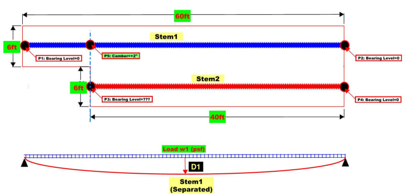
Let's assume all bearing points (P1, P2, P3, P4) are supported immediately after erection before sustained loads are applied.
As more loads are applied, P5 at the long stem1 near P3 will deflect lower than P3. (P3 cannot deflect because of bearing support.)
So, some portion of applied load to P5 will be transferred to P3, which means shear/bearing force at P3 will increase.
(Basically, long stem is hanging on short stem around P3.)
However, as long stem will deflect more than short stem near P3/P5 due to prestressing force,
short stem near P3 will hang on long stem near P5 unless P3 is supported by something.
Therefore, the load transfer of odd shape double tees depends on the support condition at the reentrant.
What do you think about this analysis?
DT_Load_Distribution-3_hsaa10.jpg

JRW
 
What is the goal of knowing the load distribution? I agree with Koot's simple span approach, and believe that is the industry norm. You mentioned yourself you expect the strand layout to be the same in each, and I doubt the end reinforcing in the anchorage zone changes except when the section depth changes. You would need to check, but the potential increase in shear does not seem to be a problem for the cross section. I believe my analysis suggests a far greater load transfer than can happen. We have not even started to talk about the elastomeric bearings. A double tee is simpler to analyze.

I searched the entire PCI website yesterday and did not find any studies related to this. In the bridge world you can find skewed bearing studies that might be of interest. I did find a few studies about vehicles driving over the joints between sections.

This study on torsion in Double Tees by Dr. Stanton may be of interest to some. Double Tee
 
Brad,

My goal is to calculate supporting load at P3 manually/reasonably.
I am looking for better method or model which can provide this info.

Thanks!

JRW
 
Ok, I have no good ideas for the manual hand calc solution. I did re-run the model as a double tee. Once you remove the 25mm gap, there is very little non-linearity in the model. I believe I could replicate those results in SAP2000 reasonably well using three shell elements, but that is not manual.
 
JR said:
What do you think about this analysis?

I like it.

JR said:
My goal is to calculate supporting load at P3 manually/reasonably.

I'm not sure that's possible considering a partial listing of the complexities involved:

1) Much depends on torsional stiffness which drops very low -- and very unpredictably low -- once torsional cracking initiates.

2) Much depends on the effective flange width that participates in dragging shear between the two members.

3) Much depends on the presence, or absence, of hold down connections where a tee stem would be put into uplift by the load sharing.

4) Much depends on whether or not either piece is shear connected to a neighboring member... or two... or three opposite the interface of concern.

At best, you might attempt to estimate an upper bound on the shear transferred between the two members assuming that each is perfectly torsionally restrained and that the shear transfer is limited by flexural yielding on an aggressively chosen effective width of each flange.
 

I guess this topic used be hot in the bridge industry before.
There seem to be some researches and papers released in the past.
When I read a paper, it mentioned LRFD AASHTO.
I guess new AASHTO incorporated what these past researches had found...
 
Status
Not open for further replies.

Part and Inventory Search

Sponsor