Continue to Site

Eng-Tips is the largest engineering community on the Internet

Intelligent Work Forums for Engineering Professionals

  • Congratulations cowski on being selected by the Eng-Tips community for having the most helpful posts in the forums last week. Way to Go!

Location of pilecap bottom reinforcing 1

Status
Not open for further replies.

ChiefIlliniwek1

Structural
Aug 13, 2013
6
I am designing multiple pile caps supporting round storage silos to bear on top of steel H-piles. Due to the lateral loads, I would like to consider my piles as fixed at the top for the connection to the pile cap. I've followed a Colorado DOT standard for the embedment of my H-pile into the pile cap, 20" for a HP12x53. I also have some high capacity piles currently sized at HP16x121, but the size of those is likely to decrease. I haven't yet calculated the embedment for those, but I need to keep those in mind also.

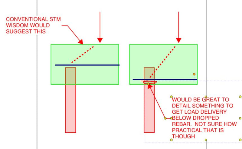
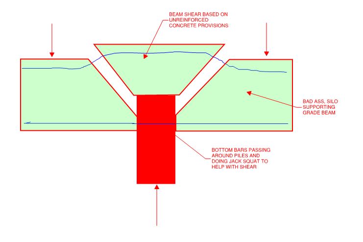
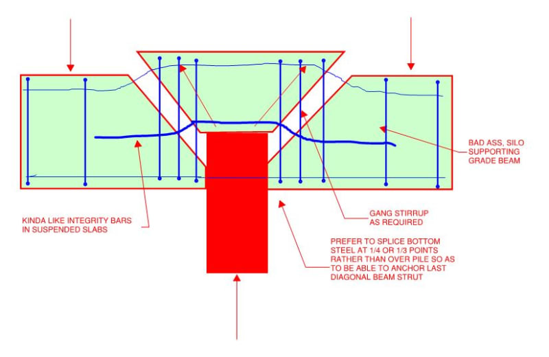
My question is, where do I locate my bottom mat of reinforcing? I cannot for the life of me find any guidelines for this situation. CRSI locates the bottom mat of the cap a few inches above the top of the pile. For my 54" thick mat, that puts my bottom mat over 24" from the bottom of my cap. If the piles are directly under the silo ring, do I need to consider a strut and tie model? I can see how this might get problematic considering the piles are in a circular pattern and potentially with the height of the theoretical model cut down due to the bottom "tension" chord being at such a shallow height.

If I put the bottom mat near the bottom of the cap similar to a standard footing, I would have to have continuous large bars at large spacings to clear the piles. Can I decrease the spacing of my bottom bars and terminate them at the piles? They're not required to develop the full strength of the bars directly at the pile locations.

All help is appreciated!
 
Replies continue below

Recommended for you

You certainly need to make sure the piles don't punch out of the top of the pile cap, so locally to the piles you need to be able to drag/strut the tension or compression forces in the pile up or down to engage both mats of reinforcement to deal with any moments in the pile cap that result.

I'd say intuitively the reinforcement should be at the bottom with an appropriate cover. Then deal with the load path from that perspective given the loads are presumably resisted via end bearing on the concrete 20" into the pad or though studs or bars welded to the flanges/web/cap plate of the H-piles.

You can provide some standard sized holes through the pile flanges or web so that you can pass continuity bars through the section to maintain the continuity of the typical reinforcement cage spacing. The other option is you have a band of reinforcement (equivalent to that which was displaced by the pile) placed locally to the sides/edge of the piles in each direction, but this might be harder to achieve given the circular layout of the piles.
 
The bars should be placed as for a footing, certainly not over the steel piles. You could probably terminate some bars where the hit the piles, but I would add some lapping bars at those locations.

If the piles are directly under the load from above, It seems to me you don't have much of a strength design problem.
 
OK. I'm in agreement about putting the bottom mat at the bottom with standard cover. I'll lap additional bars around the piles.

Agent666: I'm having a little trouble visualizing your comment in the first paragraph. Punching shear is a separate matter than developing bending moment in the top and bottom mats. Are you suggesting that I need to tie the top and bottom mats together at the pile locations with rebar?
 
SlideRuleEra: Yes, it's not much, only a few kips, but it is there.
 
ChiefIlliniwek1 - Uplift on H-piles is a concern. Unless steps are taken, friction of steel on concrete is the only force keeping the piles in the cap. Studs welded to the pile, installed after driving, work. I have used a simpler solution - a slightly oversized hole near top of pile, in the web, to allow insertion of a large, short horizontal rebar dowel. For the high uplift loads we encounter, could be a pair of dowels through holes in the flanges. Make sure holes don't compromise pile cross section needed for compression loading.

Pile cap needs to thick enough (compared to it's horizontal dimensions) to act as a rigid plate. Otherwise load distribution to individual piles will vary from calculated values.

Embedded piles apply force to the inside of the pile cap. The top, bottom, and sides of the pile cap need to be well reinforced to contain this loaded concrete. See "Investigation of the Strength of the Connection Between Concrete Cap and the Embedded End of a Steel H-Pile" (attached). This 1940's research by the Ohio DOT remains valid today.

[idea]
 
Depends on what you're doing and what you need the cap to do.

For moderate vertical bearing and small lateral loads, placing the mat over the piles can be easier. If you are trying to pass larger lateral loads and transfer moments at the pile head, you'd generally want the mat lower than the pile tops, but possibly not depending on how you detail the system. If you have a deep embedment, or are controlled by a significant moment where you need every inch of depth, you might want to get the steel as low as possible.

It also depends on how much extra work putting the rebar below the top of pile is. For small piles that can be installed accurately in a open spacing, it might be easier to go below the top of pile. For tight, larger diameter piers, that might take more work.

For large vertical loads, you might want it there to help with confinement, or you might have specific detailing to ensure confinement.

So... my answer is "it depends"

 
OP said:
CRSI locates the bottom mat of the cap a few inches above the top of the pile.

They do. And I believe that there is an important technical reason for that. And it pertains to these crucial comments.

Agent666 said:
You certainly need to make sure the piles don't punch out of the top of the pile cap, so locally to the piles you need to be able to drag/strut the tension or compression forces in the pile up or down to engage both mats of reinforcement to deal with any moments in the pile cap that result.

SRE said:
Embedded piles apply force to the inside of the pile cap.

It is a massively important, yet somehow little publicized, tenett of concrete design that loads and reactions are to be delivered on opposite sides of the member. And, by implication, loads and reactions should be outside of the flexural reinforcing. If your pile reactions are delivered near the tops of the piles, and you drop the rebar low, you will be in violation of this. That doesn't mean that the bars can't be dropped below the level of the pile reactions but it does mean that some careful consideration must be given to the punching shear issue that the other guys have mentioned above.

OP said:
do I need to consider a strut and tie model?

Meh. Given the proportions of most pile caps, it's pretty hard to argue that they all shouldn't be done with STM. That said, STM is time consuming and I mostly still see these things getting designed via sectional methods or semi-sectional methods as with the CRSI stuff. That said, if you were to do the STM, I think that you'd arrive at something similar to what I've shown below and that would get you wondering about placing the bars at the bottom of the cap. More complex models can be developed to make a go of things with the rebar low but you've pretty much got to sort those out yourself as you aren't likely to find them anywhere in print.

Some additional thoughts:

1) It would be great if you could move the pile axial reactions down to the bottom of the cap somehow as I've shown below. I'm not sure how practical of a solution this is though.

2) I've seen research to indicate that pile reactions can be transferred into the concrete very quickly via bearing and skin friction. So, even with the deep embedment, you may not actually be delivering the pile loads deep into the cap. That said, however, it would be unnerving to put too much stock in delivering your loads somewhere other than where the end bearing is unless you're taking measures specifically designed to distrupt end bearing (which would be weird and probably ill-advised).

3) A straight, slab style punching shear check on this is likely to quite unconservative for two reasons:

a) depending on your code, consideration may not be given to the size effect which tends to make thicker slabs proportionally weaker than thin ones for shear.

b) the punching shear frustum will probably not intercept the flexural compression block which is where much of the shear capacity is developed.

c01_lfbt8i.jpg


HELP! I'd like your help with a thread that I was forced to move to the business issues section where it will surely be seen by next to nobody that matters to me:
 
Slide Rule Era: I had already added studs to the piles to pick up the uplift loads. I'll review that document. Thanks for adding it.

TLHS: I have both 12" and 16" HP sections. I can probably get around the 12" HP sections, but the 16" HP sections meet that I'll certainly be around 18" bar spacing, which is not ideal.

KootK: I know almost enough about strut and tie to be dangerous, but am not well-versed. Every S&T model I've seen is delivering a point load similar to a truss, with the struts & ties acting like truss members. Can S&T be used for beams that have a uniform distributed load? That's more similar to what I'm dealing with. Please see my note below.

I have circular silos that are going to be placed directly on top of piles that are driven in a circular pattern. One pile cap is going to be a traditional rectangular cap with HP12s with three shared silos. There will be a different cap which will be a circular ring beam on top of HP16s. So I have two different scenarios to consider.

Having the mat above my piles which are embedded 20" into my pile just seems off. Given the nature of my industry and other engineers, I'm sure it would get a lot of questions. I think having the piles penetrate the bottom mat is probably the way to go. I may revisit the idea of fixed head piles though, depending on how the rest of this thread goes.

 
OP said:
Can S&T be used for beams that have a uniform distributed load?

Yes. You'd just take your uniform load and transmogrify it into some equivalent point loads at your nodes. Really, this is usually the case for "real" trusses too unless your doing some sexy timber / industrial thing where your secondary framing is planned to land right at the notes.

op said:
Having the mat above my piles which are embedded 20" into my pile just seems off. Given the nature of my industry and other engineers, I'm sure it would get a lot of questions

I didn't say that you couldn't put your bars low. What I'm saying, is that if you have real grade beam loads that need to get over to the piles and you do put your bars low, you'd better have one well though out answer to the failure mode shown below. Otherwise, you're going to be one super-sorry-chieftain. This comes up all the time in my neck of the woods with grade beams on screw piles. The nature of screw piles is that their usually capped well above the bottom steel of the grade beam.

c01_jw95r3.jpg


HELP! I'd like your help with a thread that I was forced to move to the business issues section where it will surely be seen by next to nobody that matters to me:
 
Just to prove that I'm into solutions as well as fear mongering. Although I am most definitely into fear mongering.

c01_tunpv0.jpg


HELP! I'd like your help with a thread that I was forced to move to the business issues section where it will surely be seen by next to nobody that matters to me:
 
OP said:
Agent666: I'm having a little trouble visualizing your comment in the first paragraph. Punching shear is a separate matter than developing bending moment in the top and bottom mats. Are you suggesting that I need to tie the top and bottom mats together at the pile locations with rebar?

Basically what Kootk said (especially his last sketch was exactly what I was thinking & what I was getting at with my comment). Reliance alone on punching shear capacity when you aren't wholey applying the load to the member in a traditional way to the compresison face requires a bit more thought. A strut and tie model of the load acting upwards at the top of the pile leads you to what reinforcement resists this in tension to engage the bottom bars.

Often in standards there are requirements for example where a load is introduced at the bottom of a beam (say from another beam supported perpendicular) in the tension region that you need sufficient 'hanger' reinforcement within the width of the incoming beam and some proportion of the depth either side to drag the incoming reaction up to the compression face, kind of like your situation (the additional stirrups Kootk noted act as hanger reinforcement). Often in these regions you need a few more concentrated stirrups or similar to deal with the reaction and get it into the normal strut and tie truss for the supporting beam.
 
If I may ask, why do you need a fixed head for a silo? I would expect predominantly vertical loads from overturning and dead load, with comparatively smaller base shears. If you have a reasonable base shear, is there uplift?

I'd consider what's most critical. You want to deliver moment deep into your section, you want to deliver compression to the bottom, you want to deliver tension near the top. They're a little bit conflicting. You can start welding bearing plates or rebar to things to help push stuff around, but that's obviously never ideal from a constructability standpoint.
 
TLHS said:
If I may ask, why do you need a fixed head for a silo? I would expect predominantly vertical loads from overturning and dead load, with comparatively smaller base shears. If you have a reasonable base shear, is there uplift?

You know, I'm really questioning the decision to make them fixed. I think it was originally decided due to the equipment related to the silos, and likely some faulty preliminary modeling. Looking at the reactions vs the applied loads, I've got some piles that are taking more than their fair share of horizontal loads. I'm wondering if the fixed head assumption is worth it or not. It's something I'm going to have to look at.

There is uplift that has to be considered due to the small diameter of the silos compared to their height. However, it's only a few kips and can be managed easily.
 
Regardless of where you put the horizontal mat of reinforcing, if your piles are near the edges of the pile cap, you will also need to consider reinforcing for lateral confinement of the piles.
 
HotRod10 said:
you will also need to consider reinforcing for lateral confinement of the piles

I am following CRSI guidelines for edge distance, and using their minimums. Their guidelines use 3000 psi concrete, but I'm specifying 4000 psi concrete, so these distances should be conservative. It's interesting to me that there are no readily accessible design guides for pilecaps. Everything seems to be more or less prescriptive, or you have to go full out S&T methods. One would think that ACI or someone else would have come up with design guides for figuring out lateral edge clearances, punching shear, or mat placement by now.
 
I'm not familiar with the edge distances from the CRSI guidelines, nor whether they are intended to prevent breakout of a pile with full moment applied. I suggest looking at CDOT's reinforcement details for pile caps where they're using that 20" embedment you mentioned.
 
ChiefIlliniwek1 - I'll offer thoughts on this project that may be inappropriate. If so, please ignore them.

Appears the intent is to compromise the designs to minimize the total number of piling needed; this can have unintended consequences.

With uplift on some piling, compression loading on other piling will increase correspondingly. With a minimum number of piling there is little, if any, reserve capacity for unexpected (geotechnical) failure of one or more piling. You have already mentioned problems with anticipated horizontal load distribution.

The HP16s are way over twice the weight and crossectional area of the HP12s. A pile hammer suitable for HP16s may be too powerful for HP12s... or if the hammer is "good" for HP12s, too "weak" for HP16s. Think higher than expected construction costs for two sets (different size cranes & hammers) of equipment.

Suggest going with one size HP for the project and increasing the number of piling to allow lighter pile loading. Of course, larger foundations needed... money well spent.

Pile foundations are both structural and geotechnical elements at the same time. I've encountered, and dealt with, a lot "troubled" pile foundations because the OER's design addressed only structural... or only geotechnical concerns.

[idea]
 
Status
Not open for further replies.

Part and Inventory Search

Sponsor