Eng-Tips is the largest engineering community on the Internet

Intelligent Work Forums for Engineering Professionals

Locked Rotor Time (Tre Vs Te) 3

Status
Not open for further replies.

NickParker

Electrical
Sep 1, 2017
396
0
16
NL
What is the difference between the locked rotor time tRE Vs tE? as tRE is mentioned as 35s and tE is 8s in the motor datasheet.

Te_t70e6c.png
 
Replies continue below

Recommended for you

Did the specification writer know that when he wrote the specs, before the motor was sold?

--------------------
Ohm's law
Not just a good idea;
It's the LAW!
 
NickParker: waross is correct - tRE is for "reduced voltage" condition. Specifically, for the 80 percent voltage condition dictated in the line immediately preceding the one you "snipped" an image of. tE is the "full rated voltage" condition. When the motor starts, it will draw some instantaneously high current (lock rotor current) for some time - as long as the current draw is high, the line voltage at the motor terminal will be reduced. If you have a fairly stiff system (or a relatively small motor), the drop won't be very much - but it will be something. All the motor OEM is telling you is that the motor is capable of starting at UP TO 80% line voltage (20% dip) - it just takes MUCh longer to come up to speed.

Converting energy to motion for more than half a century
 
It's just another data point using a reduced voltage start. Might be 80%.

What voltage is required for the motor to start depends on the load the motor is driving. With no load, it'll start with less than 80% voltage no problem. With certain loads, 80% voltage would be a big problem.

 
Maximum locked rotor time at DOL = 8 seconds.
Maximum locked rotor time at 80% reduced voltage starting method = 35 seconds.
Not starting time but stalled time (Locked rotor).
Anecdote Alert:
We had an issue years ago with a lumber planer.
When a board jammed in the planer, the friction of the knives may boil the moisture in the wood.
This would cause the wood to expand/explode. (Contained within the machine)
That would jam and stall the 40 HP planer knife motors.
Even though are locked rotor time with those NEMA frame motors was more than 8 seconds, we did occasionally suffer motor butnouts.
We solved the issue with zero speed switches that disconnected the motor immediately when it was stalled.
When the "T" frame motors started to replace the NEMA frame motors, we were concerned with the short allowable locked rotor times, in the range of 8 seconds.
The control for the feed motor of the planer had two buttons;
START and JOG REVERSE.
In the event of a jam-up, the operator would immediately plug the feed motor into reverse to try to clear the board before it exploded.
Don't try that with a "T" frame motor.
I miss those old NEMA frames. They were rugged motors.

--------------------
Ohm's law
Not just a good idea;
It's the LAW!
 
tRE is when the speed sensor confirms that the motor is picking up speed (having been started) and thus has some cooling through the shaft mounted fan.
tE is when motor shaft is stalled, could be either stall during start or stall during run and thus has no cooling.
This terminology applies specifically to 'increased safety' motors for Zone-II hazardous area classified application I suppose.
The motor needs to be positively isolated within tE time on sensing stall condition so as not to exceed the temperature limit as prescribed by Temperature classification(T-class).
 
RRaghunath - that sounds correct.

Locked rotor going from 8s @ 100%V to 35s @ 80%V seemed highly unlikely. I was highly doubtful that 35s was the locked rotor time at 80% voltage.

 
Waross

1964 - T-Frames were introduced (same frame sizes today)
1954 - 1963 there were "U-Frame" - heavy duty, cool running, built like tank
Pre 1954, just called Pre-U-Frame motors - frame sizes were different from each motor mfg.

Mac
 
Thanks for the clarification, macmckim.
When the T-frames came in, plugging switches went out.
Back in the days of the U-frame motors, I had a 20 HP U-frame overloading and tripping out.
I replaced it with a pre-U-frame 25 HP motor.
The next jam-up, that old motor just kept turning instead of stalling and tripping off.
It ripped up so much machinery that the plant was down for three days.

--------------------
Ohm's law
Not just a good idea;
It's the LAW!
 
RRaghunath said:
tRE is when the speed sensor confirms that the motor is picking up speed (having been started) and thus has some cooling through the shaft mounted fan.
tE is when motor shaft is stalled, could be either stall during start or stall during run and thus has no cooling.

from the datasheet,
tE - 8s
tRE - 35s

On one hand it should be isolated within 8s, on the other hand the speed sensor confirmation is at the 35th sec - It is confusing.
What am I missing?
 
As a suggestion, will this fit the application?
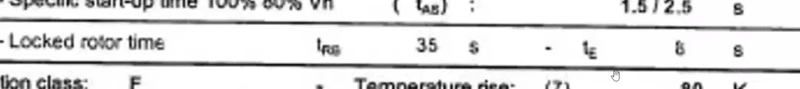
First stage, isolation at 8 seconds.
Second stage, first stage isolation disabled by speed sensor, isolation at 35 seconds.
Not given; Time to allow speed sensor inhibition of first stage isolation.
Eg: At 8 seconds of complete stall, all of the allowed thermal capacity of the motor has been used.
For example, the extension of time may have to see rotation within the first second after energization.

--------------------
Ohm's law
Not just a good idea;
It's the LAW!
 
Status
Not open for further replies.
Back
Top