Continue to Site

Eng-Tips is the largest engineering community on the Internet

Intelligent Work Forums for Engineering Professionals

  • Congratulations waross on being selected by the Eng-Tips community for having the most helpful posts in the forums last week. Way to Go!

Long Span (35') LVL Beam Design 8

Status
Not open for further replies.

Brobocop

Structural
Dec 27, 2019
17
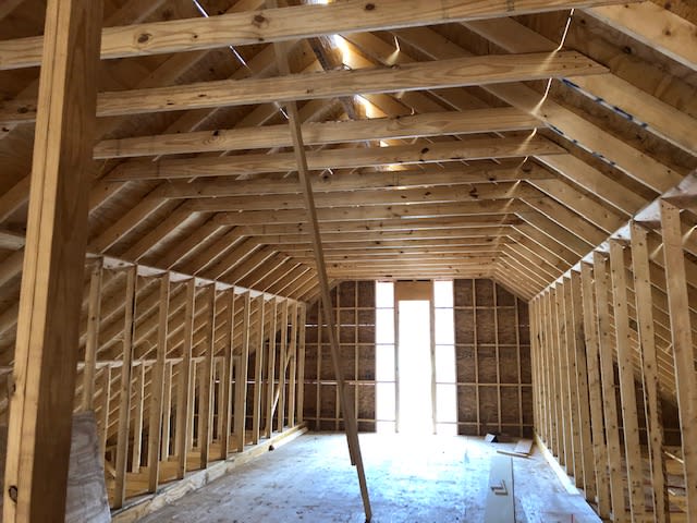
I was contacted by a building owner that wanted to build out his attic space into offices, and needed to ensure that 2 installed beams (Beam were never previously Engineered) are adequate to handle the additional live and dead loads.

There are two beams in question, each comprised of Four 2x16 LVLs fastened together and 35 ft in length. They are supported at the ends by two 5.5"x5.5"x0.25" Square HSS. The rest of the ceiling is framed laterally with 2x10s 16" o.c.

Rather than Model the entire building, I modeled just column/beam frame (diagram attached), and am wanting to put the distributed dead, live and wind load on the beam for my analysis.

My STAAD model results are currently showing Fail, and also a mid-point Deflection of about 3" (L/140).

Looking at the roof framing, is the rafter bracing wall - that sits directly onto the beam - picking up much load? or does most of the roof load go to the exterior walls? I'm making sure I'm accurately calculating all loads before recommending a different solution (Being that the beam is currently installed).

35' is a heck of a span to begin with. Not many LVL manufacturers have spans listed that high in their literature.

I appreciate the insight.
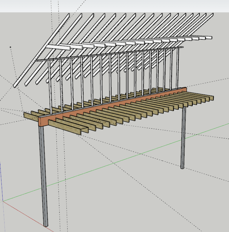
SketchUp_rz1hue.png


STAAD_Model_dt91y0.jpg


Beam_2_arlg2u.jpg


Beam_3_pj6cfk.jpg


Beam1_bqregw.jpg


Looking_South_West_pybuje.jpg


Looking_North_oyduyx.jpg
 
Replies continue below

Recommended for you

Brobocop said:
So now you would effectively have a 40” deep LVL beam?

Only if you connected them together to make them act compositely - possibly by sheathing the sides of them. Much easier to design them as a 16" and 24" beam with compatible deflections.
 
Brobocop said:
Is there any potential retrofits to the existing Timber beam that would work? Maybe building up the section to have the 21” depth?

Modifying the existing beam creates the composite action connection problem that XR250 mentioned.

Something else to consider: It is becoming more obvious that this house was not "engineered" at all, just "built". In all likelihood, the end supports of the existing LVL are "sitting" on a nominal 4" concrete slab... not a suitable foundation. This needs to be addressed... adding column(s) to distribute some load (to appropriate footings) will help alleviate end support loading, but will not solve it.

Another thing to look at: Even if the space is not used as an office but only an "attic" (with much lighter live loading), I doubt the existing LVLs will be acceptable (because of deflection) when wind loading is added (as it should be). And if you do look at wind loading, consider both of the LVLs at the same time. Since they support opposite sides of the the roof, wind pressure (therefore force applied to the LVLs) will be very different at any moment. The entire floor (whether "attic" or office) is going to be like a self-excited trampoline during a wind event.

[idea]
 
Ask the owner for permit to do this job. Most wood and connectors are looking new, isn't this a half way done new construction? Where was the design?
 

Yes. This was half way done and the beams were installed when I was called. I was asked to verify the beam size after the fact. The permit was approved for the original design, unfortunately the permit was approved without any engineering of the beams.

Then once the building was built, the owner wanted to convert the attic to an office. They contacted me to verify that the beams would be adequate for the "Change in use"... Unfortunately, it looks as if they are not even satisfactory for existing use (attic).
 
You got a bigger job and responsibility. Talk to the owner with your finding, and alternatives. Unfortunately, he got to pay for his own mistake (selected an un-competent designer).
 
Also, it looks like unavoidable to inspect and evaluate the entire building structure, as the previous designer might have just pick a standard drawing set for similar house without thinking he's dealing with non-standard dimensions, thus, other items might have been under sized as well. The trouble is the foundation that you couldn't see. Hope there is record drawing available.
 
I like XR250's idea of a second beam on top of the existing LVLs with sheathing on both sides to get composite action.

It will be a real pain to get 24" deep LVL's up there though. Another small issue is that the electrician is not going to be able to put normal height plugs down those kneewalls after you double the beam.

Here's an outside the box idea that might let you use smaller sections. It would require more analysis and STAAD work though.

What if you made a giant site built truss? This would solve your depth to span issues; and hopefully let you use some smaller size lumber for the retrofit.

You could cut off a larger section of the kneewall (maybe ~36" tall) and insert another 4-ply LVL Beam. The new beam will be the top chord of your truss, and the old beam will be the bottom chord. The struts and tie webbing could be filled in with multi-ply 2x6's with steel connecting plates. And then the whole thing could be sheathed for good measure.

Regardless of how you solve the framing issues, I do think you need to investigate the slab/footing that the posts are sitting on. If you just have a 4" slab down at the bottom, then you are going to have to address those issues too.
 
Thank you everyone for your input.

The solution that we have reached will be to shore the ceiling, and install a new, properly sized LVL beam in its place, more than likely 24" in depth. The Contractor agreed it will be the easiest option to construct, because he can install it one ply at a time. Once the plys are erected, he can then fasten them together per manufacturer specs.

I've seen the foundation plans. There are footings beneath all 4 columns.

It will be quite a job for the contractor!

Thanks again.
B-Cop
 
Make sure the columns and footings were properly sized.
 
So this brings me to my next question.

Are these beams considered floor members, or roof members?
 
I vote floor member, as they were not required for the roof, if the walls were not constructed all the way to the underside of the roof.
 
Would you believe me if I said the beams need to go from 7"x16" to 10.5"x22" ?

Because this is where my calculations are leading me. 6-Ply 1.75" LVL 22" tall.
 
Do you have anybody can help to check your work? Just to make sure nothing has missed. I will kick myself, if I am the owner :)
 
If I didn't make mistake, from 8"X16" - 10.5"x22", you have reduced the deflection from 3" to 0.875" (L/480). Is this what you want?
 
For that size, deflection is no longer controlling. It's the stress in the beam.
 
I believe you were surprised for the result too. Just be prudent, that's all I can think of right now.
 
Brobocop said:
The solution that we have reached will be to shore the ceiling, and install a new, properly sized LVL beam in its place, more than likely 24" in depth. The Contractor agreed it will be the easiest option to construct, because he can install it one ply at a time. Once the plys are erected, he can then fasten them together per manufacturer specs.

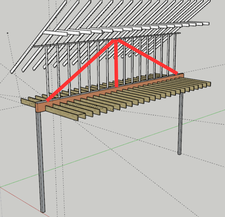
A better and easier solution in my opinion is to provide truss members above the existing LVL beam as shown diagrammatically below. The sloping members could be installed within the wall which would mean cutting all of the studs to accommodate a single member. Or, the sloping members could be double members, installed one on each side of the existing studs. The vertical tension member at midspan would be installed within the wall.

LongBeam_qptkeh.png


BA
 
BA Retired's truss idea is better than my truss idea. His is a king post trust and I was thinking a Pratt truss. The king post is much simpler and doesn't require a top chord beam.

These truss ideas seem a lot easier to me. If you remove all the existing joists, the joisthangers will probably all be toast. They will get all bent up in the removal process. Not to mention the headaches involved in all the temporary shoring.
 
Brobocop,

I've seen the foundation plans. There are footings beneath all 4 columns.

What is width of the building? 35' is a quite long span, can the side walls survive without intermediate columns? Also, you didn't show the edge beams, how sturdy are they to span 35'? Please do not take this lightly, I felt there are traps all over the house.
 
Be careful going to a 6-ply LVL. I vaguely remember reading that the manufacturers don't recommend more than 4-plies, especially in side loaded beams (like what you have). The reason is that the load transfer between plies gets difficult to justify as it spreads across the beam and you can end up overloading the fasteners holding it together or getting localized peak stresses in the outer plies with lower stress in the center plies.
 
Status
Not open for further replies.

Part and Inventory Search

Sponsor