Continue to Site

Eng-Tips is the largest engineering community on the Internet

Intelligent Work Forums for Engineering Professionals

  • Congratulations waross on being selected by the Eng-Tips community for having the most helpful posts in the forums last week. Way to Go!

Long Span (35') LVL Beam Design 8

Status
Not open for further replies.

Brobocop

Structural
Dec 27, 2019
17
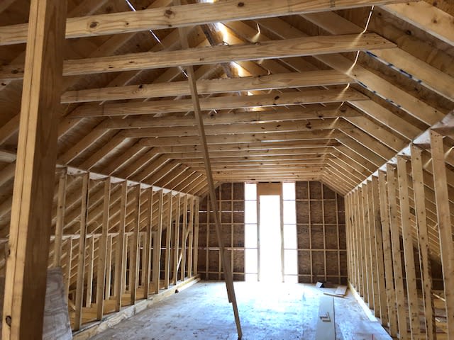
I was contacted by a building owner that wanted to build out his attic space into offices, and needed to ensure that 2 installed beams (Beam were never previously Engineered) are adequate to handle the additional live and dead loads.

There are two beams in question, each comprised of Four 2x16 LVLs fastened together and 35 ft in length. They are supported at the ends by two 5.5"x5.5"x0.25" Square HSS. The rest of the ceiling is framed laterally with 2x10s 16" o.c.

Rather than Model the entire building, I modeled just column/beam frame (diagram attached), and am wanting to put the distributed dead, live and wind load on the beam for my analysis.

My STAAD model results are currently showing Fail, and also a mid-point Deflection of about 3" (L/140).

Looking at the roof framing, is the rafter bracing wall - that sits directly onto the beam - picking up much load? or does most of the roof load go to the exterior walls? I'm making sure I'm accurately calculating all loads before recommending a different solution (Being that the beam is currently installed).

35' is a heck of a span to begin with. Not many LVL manufacturers have spans listed that high in their literature.

I appreciate the insight.
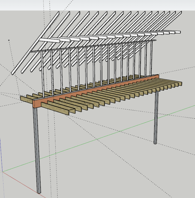
SketchUp_rz1hue.png


STAAD_Model_dt91y0.jpg


Beam_2_arlg2u.jpg


Beam_3_pj6cfk.jpg


Beam1_bqregw.jpg


Looking_South_West_pybuje.jpg


Looking_North_oyduyx.jpg
 
Replies continue below

Recommended for you

The top plate appears to be sloped to match the slope of the rafters. If P is the compression in each stud, the connection of rafter to plate and plate to stud must be capable of resisting a force parallel to rafter of Psinθ where θ is the slope of the rafter. This may require more than toe nailing between rafter and plate.

SlopingTopPlate_ootl5q.png


BA
 
Brobocop said:
Would you believe me if I said the beams need to go from 7"x16" to 10.5"x22" ?

Because this is where my calculations are leading me. 6-Ply 1.75" LVL 22" tall.

Yes I would. I = 9,316 for (6)22" LVL versus 10,417 for the (4)16" and the (4)24" on top (non-composite) as I previously suggested. This is by far your easiest fix. Stay away from the truss idea - the connections will be super difficult to make work.
 
XR250 said:
Stay away from the truss idea - the connections will be super difficult to make work.

Only if the designer lacks imagination.

BA
 
Seems likely the owner would want access through one or both walls for office storage.

BA
 
BAretired said:
Only if the designer lacks imagination.

Agreed. No offense to the OP, but using STAAD for a simple beam problem and some of the questions he has asked, has me questioning his ability to tackle the truss design.
 
XR250, my thoughts exactly. Why in the world are we "modeling" simply supported beams with uniformly distributed loads in STAAD? Scary!
 
Makes a pretty picture? (I've modeled things for that reason before - client was impressed by a 3D, color coded stress rendering so I built simple models of projects I did for them and they always like it.)
 
You could fasten however many layers of 24" LVL you need to the outside faces of the wall studs. That would make the room 1.75" narrower for each wall. Placing these directly over the existing LVLS seems like a possible solution.
 
phamENG, yes, it does make a pretty picture. I will give you that.
 
Ron247 said:
You could fasten however many layers of 24" LVL you need to the outside faces of the wall studs. That would make the room 1.75" narrower for each wall. Placing these directly over the existing LVLS seems like a possible solution.

That sounds like a great idea. The problem with a 7"x24" built up beam, is the large L/b value (35x12/7 = 60) with no clear way to provide lateral or torsional bracing . With Ron247's idea, the existing studs provide excellent bracing for all four members. And the other advantage is that the existing walls above the beams do not have to be removed...great idea, Ron.

Using Ron's idea, the existing beam could be supported by hanger rods spaced, say at 4'-0" centres running up through the bottom plate and up to the four foot level where they would place the load on the upper two LVL members.

BA
 
BAretired said:
The problem with a 7"x24" built up beam, is the large L/b value (35x12/7 = 60) with no clear way to provide lateral or torsional bracin

That is why i stated that kickers be installed from the top of the beam to the floor system behind the kneewall.
Ron's idea is also a possible but still has to get the end reaction down to the columns. Also would have to fur - out the interior face of the studs for aesthetics.
 
@XR250,
Yes, kickers would work but clutter up the potential storage area outside the wall (which may or may not be an important consideration for the owner).

I don't know the detail of the cap plate on the column, but reaction from the upper LVLs would flow down directly through the outer lam of the existing beam to the cap plate. Some beefing up of the column and cap plate may be required to compensate for a heavier live load than previously considered. The Office floor joists should also be checked for office loading.

BA
 
If the existing LVL is to remain in place there are some additonal issues that need to be addressed. Here are a few:

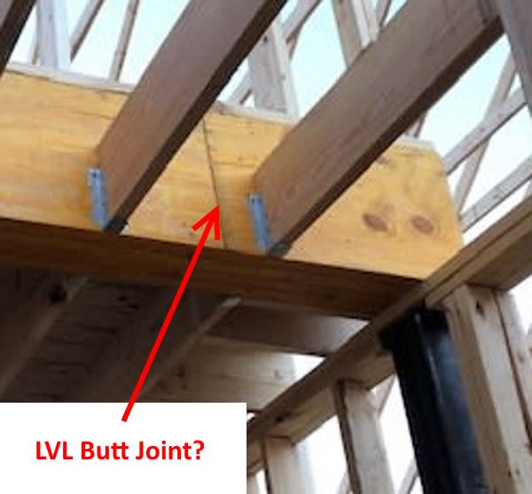
1) Is the existing LVL really 4 plys that are, 35' long? Or is it shorter LVLs that have been spliced together, with the splices located at "random" locations. This photo raises that question:

LVL_Splice-600_zekvum.jpg


2) The heavily loaded column (estimated 7+ kips) does not have a properly sized (steel) bearing plate and is eccentrically loaded by the LVLs:

Bearing_Plate-600_r25ul9.png


3) The office floor joists are not framed into the LVL. Instead there is a rim joist. How is the rim joist connected to the LVL?
Also, the LVL loading is eccentric, since the unoccupied attic loading is minor compared to office and roof loads.

Eccentric_Loading-800_lqebpd.png


[idea]
 
SlideRule,

1) That butt joint is probably a factory joint between two thin layers of veneer. I have seen them frequently on LVL's in the field and at first glance they do look like a butt joint between LVL pieces.

2) I agree that the bearing area does not look great, but I don't see that much eccentricity, although whatever eccentricity is there, I am sure that it has not been accounted for.

3)I agree that the ledger connection to the LVL should be checked.
 
Sliderule,
On second thought, I still think that butt joint could be a factory joint between two thin pieces of veneer, but on the other hand, 35 foot long pieces of LVL, while available, are pretty long and pretty uncommon and would pose a delivery problem for some residential contractors, so you may be right that it might be a butt joint between two pieces of LVL.
 
Not sure why there is a ledger. I thought all joists were connected directly to the beam using joist hangers. The ledger may be just 16" long in which case it is a deck support and is not heavily loaded but that should be checked on site.

I missed the fact that the wall is eccentric to the beam (thought they were both centred over the column). Looks like some modification to the column and cap plate will be required.


BA
 
gte447f & BA - I agree, the few photos provided don't prove anything, but sure point out details that need to be checked considering known problems.

IMHO, there are plenty of other things the OP should consider:

Depending on the width of the office (looks like about 14' to me), are 2x10s @ 16" o.c. floor joists may be overloaded at 50 lb/ft[sup]2[/sup] live load + dead load?

Rafters look a little "small" for their span.

Compression flange of the existing 35' LVL is not really braced anywhere. Top of the 2x10 is a little above mid-line, but not much.

If the OP really does go with a replacement 6-ply, 22" LVL, most of these potential problems get even worse and new problems arise.

One more piece of advice, if the OP returns to this thread... be careful when considering any "advice" from the contractor. He is most likely the d--m fool that created this mess... that you are about to take engineering responsibility for.

[idea]
 
SRE,
Yes, there are a lot more factors to consider than first appeared. I am wondering who prepared the drawings from which the contractor is building. Seems very unusual to specify 35' long LVL beams without doing some analysis.

The OP seems to be showing very little interest in our comments so far...maybe I'll do the same.

BA
 
gtw447f said:
On second thought, I still think that butt joint could be a factory joint between two thin pieces of veneer,
Looks like a factory joint to me
 
Status
Not open for further replies.

Part and Inventory Search

Sponsor