Continue to Site

Eng-Tips is the largest engineering community on the Internet

Intelligent Work Forums for Engineering Professionals

  • Congratulations KootK on being selected by the Eng-Tips community for having the most helpful posts in the forums last week. Way to Go!

Long Steel Ridge Beam in Residential 4

Status
Not open for further replies.

Buleeek

Structural
Sep 5, 2017
98
Hello,
I am working on a residential house with a very long (51 feet) steel ridge beam (cathedral ceiling). The gravity loads are +- 500 plf. I am looking for some opinions on how to properly connect the steel members to each other and if there are any other things to consider when such a big and long beam serves as a ridge beam in a residential home (deflection, overall stability, etc). See attached. Thank you.
 
 https://files.engineering.com/getfile.aspx?folder=9e80af2c-f2e7-4db1-ad42-61d29a541c05&file=steel_ridge_beam.jpg
Replies continue below

Recommended for you

In terms of beam bracing, phamENGs response is better than what I wrote above, which was basically not to worry about it. I think in running the numbers, it'll be shown that the bracing loads can be resisted by the diaphragm without too much difficulty, but it's probably best to check this, especially with such a long beam. And I agree that for the sake of running this calculation, it's better to not call the beam continuously braced. Perhaps for this size beam, calling it braced every 8 ft or so might be roughly the same as continuous bracing anyway. Then, the bracing load would only need to be resisted every 8 ft.

This is a good discussion concerning lateral bracing and I think I'll modify my own workflow to more purposely check this condition going forward.
 
Appendix 6 is for point bracing. These systems I believe do behave more like continuous bracing where each rafter takes some portion of axial load and transfers it into the diaphragm, so equation A-6-7 but spread out over some distance. You could explicitly design and detail point bracing in the roof and that's a fine approach, but I don't think it's how these systems are behaving generally.
 
Perhaps for this size beam, calling it braced every 8 ft or so might be roughly the same as continuous bracing anyway. Then, the bracing load would only need to be resisted every 8 ft.

For that size WF, (which is a common bridge girder size), the reduction in flexural capacity due to LTB would be negligible until the unbraced length is over 15 ft.
 
BridgeSmith, I was looking at the beam design tables in the AISC manual, and for a W27x94, the max. moment occurs at an unbraced length of about 7.5 ft (or less). Braced at 15 ft, it would lose about 25% of it's bending capacity. That would probably be ok, though, considering the beam is deflection controlled.
 
Anybody feel like this?

Bracing of Beams, Trusses, and Joist Girders Using Open Web Steel Joists, Fisher, AISC Engineering Journal, 1st Quarter 2006.

Wouldn't the plywood function somewhat similarly to the metal deck and the wood joists are similar to the open web steel joists? Or would they? Wood they?

I get that a lot of people would design this beam as braced by default with zero consideration, I'm just going to have to point out that just because "everybody" does it doesn't mean it's right. We are supposed to base our designs on generally accepted principles of mechanics.

What tends to happen is a lot of these things are not subjected to their design loads, ever, so they don't buckle. Welcome to the world of stability defects.

I hesitate calling this braced continuously (or discretely) without any say, mathematical mechanics based justification. It's just beyond the typical span, the longer the span, the more this bracing question becomes relevant.

I'd suggest the beam should have a stiffener at the bearing points as well, unless it is dealt with some other way, it's the stability/bracing of the column in the perpendicular direction that is the reason I mention this, not the web crippling or web yielding aspect of the W27. This is to me, of much more concern than some sort of (cough architectural cough) "wall spreading due to downward beam deflection" which does not appear to offer such a stability question.

If it came to it, adding a sloped steel beam mid span might be a more conventional way to deal with the stability question versus a more involved analysis. That's kind of what greenalleycat suggested, if you squint at it enough. Then you have a less debatable unbraced length of 25' in downward and uplift loading. That may feel like overkill to some, perhaps many, but the alternative is a stability based design of the deck/joists to justify it as braced, which, given the stiffness difference between steel and wood, I question.

 
Hah, I appreciate the favourable squint but restraint isn't the primary reason for my suggestion. Restraint doesn't concern me too much - I'd just weld in some stiffeners full depth st required centres and get a solid tie to a rafter or similar. I think there is so much structure there that it is a solvable problem.

My actual concern is twofold

1) 51' is a ginormous beam and would be very difficult to get to site and install, at least in my city. Splitting it into two simply makes sense to suit construction.

2) Typically we design our beams to L/? Restrictions. But on long span beams the absolute deflection becomes more critical. This leads to an overly large beam to manage deflections, being overall less efficient than two smaller beams.

And a bonus 3rd, I would expect you'd need a lateral system somewhere anyway (bring seismic here you definitely would) so I would get a 2-for-1 and put in a portal frame or two to cut the span and deal with my lateral
 
I'm not too excited about item 1. There are erectors, is it a small job? Sure. beyond the skill of the average residential framer? Certainly. Inappropriate for a carpenter to erect? Certainly. In the engineering sense, it's what they want, or whatever is reasonable to get them close to what they want with a sufficient engineering justification behind it to be safe. When somebody has a bit outlandish of a vision, you don't owe them the least expensive design a carpenter could do with a pickup truck, a wrench, and a step ladder.

I agree there's a potential challenge with item 3, but to me the built-in portal frames seems like a lot to address that. There's a pretty normal roof diaphragm there (wood structural panel), it's the end "frame" of the building that doesn't have an obvious (to us kibitz-ers) load path to ground.
 
The fessibility of erecting such a big beam (including transport logistics etc) will vary of course. May be different in my jurisdiction to yours.

I do agree that, overall, it comes down to a matter of cost. The challenge itself is actually relatively straightforward. Design a very stiff beam with an absolute (not relative) deflection limit and probably apply a gravity precamber. It's no more difficult than any other beam design in that regards.

My reluctance is based on prior experience here where people do not want to pay for the depth of beam required, and architects are unwilling to compromise their design to provide the roof depth required to hide it. So I end up splitting the beam into two to keep sizes manageable
 
Eng16080 said:
BridgeSmith, I was looking at the beam design tables in the AISC manual, and for a W27x94, the max. moment occurs at an unbraced length of about 7.5 ft (or less). Braced at 15 ft, it would lose about 25% of it's bending capacity.

The graphs in my steel manual have it starting to drop off at around 9 ft for the 36ksi and around 7.5 ft for the 50ksi, so I stand corrected. We're usually bracing for negative moments in continuous spans (adjacent to the interior piers), and the capacities are based on the AASHTO equations. We also calculate Cb, which is typically >1.5, so that's probably why we don't see the capacity reductions until the unbraced lengths get larger.
 
Well its currently deflection controlled so C[sub]b[/sub] won't do much for this one, unless we're not buying the L[sub]b[/sub]=0 due to the wood deck and joists. But in an effort to be thorough and for future re-use it's a valid point.

As I was driving I wondered about a glulam versus steel, but that's probably a non starter with the deflection control and wood, but it would be less prone to potential buckling since it's an actual rectangular section versus an I section.

As a side note while I was looking for something else I found this calculation package with an 2 ply LVL marriage beam (same concept, shorter spans and loads). Those get bolted together after the fact for shipping.

Do they design these for a 70 mph driving down the road as an open building? Or is it sheeted on the open side?

modular wood building clacs for Tulata, Oregon
 
For me, the erection from a residential contraction is the biggest issue here. I would not worry about a wood roof system bracing this beam. Not a chance a 25 ft. ish wide plywood diaphragm will have a problem with it. I would tie the rafters across the beam though either with straps above or 2x4 collars below. Overall stability of the structure does need to be addressed though.
Portal frames would add significant cost and complexity to this project.
 
I just did some really rough guesstimate numbers and I think I'm looking at a beam of ~92kg/m with a precamber of ~25-30mm upwards
That's for the 51' span (15.5m) and assuming a relatively low snow load but a windy site
This equates to 15.5*92 = 1426kg of steel

Now cutting it down to ~30' (9m) I'm looking at something ~51kg/m and 170mm shallower (yay for the architect)
This is assuming a simple span as well so you could get fancy and try to detail some continuity over the supports
I wouldn't precamber this beam
This equates to 15.5*51kg/m = 791kg of steel
But I've added two portals to cut this span down so factor them in, assume probably 35kg/m of steel
Say 3m knee, 6m apex and 8m wide so ~16m of steel x 35kg/m = 560kg x 2 = 1120kg of steel so call it 2000kg

Here, $10/kg of steel fabricated, painted, installed is a reasonable ballpark so we added $6k NZD to the build
But in return we slimmed the roof depth, made the erection and transportation safer and easier (= $$ savings back) and saved a precamber (also $)
We also have two portal frames that can help us with the lateral problem we were going to have anyway
We also have far more redundancy in the system and it is overall a lower risk job

Now, I've obviously made a lot of assumptions here (and I'm not exactly sure my portal frame size is right for those dimensions, it's a spindly looking thing) but in the context of a high quality house like this appears to be, I think it's absolutely fine
I would have zero qualms about speccing some portals in this house and would have several qualms about trying to span a ridge beam the entire way
 
I think erecting a portal frame of that scale would share the same difficulties if not more.
In my area of practice, 51 ft. span anytime over portals.
 
Interesting. Portals are done all the time here, I don't think we'd get any kick back
I've never spoken to a fabricator about a 15m+ beam for residential but I can only imagine they'd kick my ass with the traffic management requirements...
 
Pretty standard to get lumber deliveries that long here. If the site can't take it though, would have to go a different route.
 
We run into headaches with anything over about 6m, it makes precast panels difficult too
The design constraint for panels (assuming contractor won't shotcrete/in situ pour/pour on site) is the truck transporting precast which limits panel size and hence dictates connection locations etc

I've just texted a friend's dad who is 2IC at a large fabricator to see what his opinion is on a 15.5m beam so we will see if I am talking shit or not
 
If you're in the United States, the standard semi trailer is about 51' long, so a length beyond that but not by much wouldn't be all that arduous. We've also been dealing with shipping for large precast/prestressed bridge girders from time to time, as well as those monster wind turbine blades they ship across the country. The first few miles and the last few miles are the most difficult, unless you're shipping something particularly tall, which a 27" deep girder doesn't really feel "too tall", and they might ship it flat to reduce any tipping/sway/stability issues and or cross-wind effects.

These concerns about the contractor, this is NOT the engineer's job. Provided, of course, the engineer does not "APPROVE" the contractor and states that a steel erector should be used. If they want to yahoo it, get themselves killed, etc, that's their decision and their liability. You could require shop drawings to include a sealed erection plan from a steel erector, that should preclude the novice from attempting it. This is not within the purview of the typical structural engineers authority anyway, let alone the structural engineer's ability to judge the qualifications of a steel erector. That doesn't sound like a typical skill most structural engineers have. We have to protect the public, but just because I'm supposed to "protect the public" does not mean I'm supposed to chase after a man running with a stick of dynamite and a spark igniter. And if I did, it wouldn't be because I'm a structural engineer.

What I keep saying about the unbraced length, is I'm not aware of any testing or research that establishes a wood diaphragm is effective in bracing such a large steel beam for such a large span. The beam, however, is currently deflection controlled so there is some margin to the debate here, as to it being effective or not, if it were designed unbraced full length, that would clearly produce a safe design so long as the end rotation was dealt with appropriately.

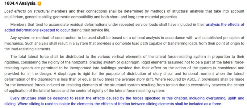
I am aware that perhaps 4 out of 5 dentists would consider the beam braced by the wood structure, perhaps even continuously braced, I'm saying there isn't much basis for that, beyond "convention", I haven't seen any research published to substantiate the practice. This is where I keep landing. There isn't a "well-established principle of mechanics" that substantiates the bracing effect. We are in the same territory, fundamentally, as the "inflection point is a brace" which was eventually disproven.

IBC_2018_1604.4_Analysis_pbizeb.jpg
 
Status
Not open for further replies.

Part and Inventory Search

Sponsor