Eng-Tips is the largest engineering community on the Internet

Intelligent Work Forums for Engineering Professionals

  • Congratulations waross on being selected by the Tek-Tips community for having the most helpful posts in the forums last week. Way to Go!

Longitudinal Shear Flow on Elastic Stress Distribution 3

Status
Not open for further replies.

FMPJ

Structural
Aug 10, 2020
11
0
0
GB
pic.jpg_zvmyf9.jpg


Hi Folks,

Anyone could please explain the principle shown on above screenshot.
I'd like to understand the relationship between the maximum longitudinal shear and maximum plate tensile resistance when assumed elastic distribution stress.
Thanks for your help.

Best Regards,
JPMF
 
Replies continue below

Recommended for you

retired13,

Contrary to what you stated, the tensile force in the plate varies from zero at the ends to maximum at midspan. It's magnitude follows a parabolic path, similar to the moment curve.

The OP does not address failure of the plate; it addresses the maximum longitudinal stress in the weld which occurs at the supports. It is an established fact that, for uniform load on a simple span, longitudinal shear in a weld varies from a maximum value at the support to zero at the point of maximum moment. If we were using stitch welding to connect the plate to the WF, the spacing would be less near the supports than it would near the midspan. Some engineers add extra weld near the supports as an additional precaution against non uniform load on the built up beam.

BA
 
Sorry, I still don't agree. The tension is applied in the mid-span, as well as where the support is located. I failed to see the stress passing beyond the support. From your present explanation, the diagram was drawn reversed, contrary to your current view - maximum at center, zero at the ends.
 
I may have misunderstood the OP's example. But, below is my understanding when tension/compression (normal stress) is involved. To weld this piece to another element, the stress in the weld should at least equal to the stress in the plate everywhere alone the length. Strengthen the ends as indicated in the text below.

image_stzsms.png
 
The diagram below shows the longitudinal shear per unit length in the weld, the beam moment and the tensile force in the plate. The units of S would be N/mm in the metric system or plf in the Imperial system.

image_a8ikab.png


BA
 
retired13,

We are not talking about P/A in the plate. We are talking about the horizontal force per unit length in the weld to get bending stress into the plate resulting from uniform load on the beam.

BA
 
Thanks for your answers folks.

I’ve got the following answer from a Boss.
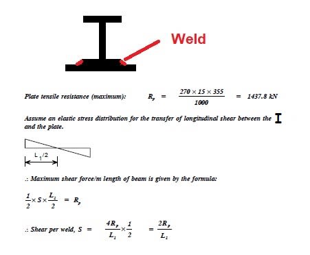
“The maximum tension in the plate is 1437 kN, at midspan. So we know the maximum longitudinal force. This longitudinal force must be transferred between the plate and member. This is clearly conservative, as perhaps the plate is not fully stressed.

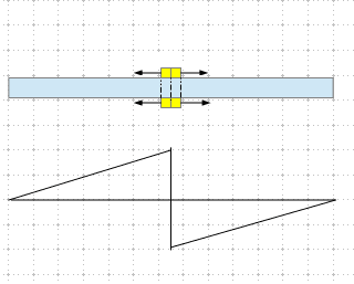
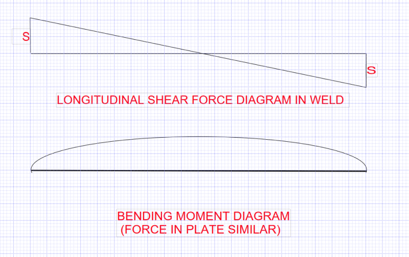
The next question is how is the stress distributed over half the span? It must have all transferred by the time you reach the end of the member. One could assume a uniform distribution, and simply divide force by length. That would mean a plastic distribution, and welds are notoriously not plastic. So an elastic distribution was chosen, zero at midspan and rising to some other value, S at the ends.

In compound sections, there is clearly no desire for “slip” between the two plates at midspan. This force (if you like, a desire to slip) is a maximum at the ends,this assumes a triangular distribution of force over half the span.

The maths is then simply working out what the maximum ordinate of this triangle is, S at the end, and simply saying the maximum longitudinal stress is equal to that value, and thus designing the weld for that value. It seems conservative and reasonable to me.”

BAretired you’re completely correct.

Thanks
 
BA,

I don't seem to understand the logic/concept in equating shear/shear flow to the tensile capacity of the connected part. For weld design, I use VQ/I for beam with uniform gravity load, My/I for pure bending, and P/A for pure tension/compression. Thanks for your relentless explanation.
 
JPMF,

Thanks, I'm glad you understand the principle.

Another way to look at it...the moment at any point x from the support is equal to the area under the Shear Force diagram between the support and Point x.

There are situations where a linear variation between support and midspan is not conservative. One such example is a pair of concentrated loads P, each distance 'a' from each end. Distance 'a' is called the shear span. Moment at point a is P*a. The moment between the loads is constant at P*a (neglecting beam weight), so the weld must develop the strength of the plate in each shear span. Theoretically, it doesn't require any weld in the central section, although normal design practice would be to provide minimal weld in all parts of the span.

BA
 
You’re welcome BAretired!

Thanks for you explanation!

Screenshot below it’s not the OP, but it’s using the same principle, is it correct BAretired?

260AFD5A-B21A-42C7-A739-CDF693BFA277_wlcwsg.jpg
 
BA said:
VQ/I is also correct. This illustrates the fact that there is usually more than one way to arrive at the correct answer.

I've made a verification calculation and find the results bothers me - for beams with any length and loaded to capacity, the shear flow from 4T/L is always 20% higher than VQ/I. As claimed before, the OP's method is conservative though.
 
retired13 said:
I've made a verification calculation and find the results bothers me - for beams with any length and loaded to capacity, the shear flow from 4T/L is always 20% higher than VQ/I. As claimed before, the OP's method is conservative though.
f = average fibre stress in plate at midspan;
T = tensile force in plate at midspan
y = distance from centroid of built-up beam to c.g. of plate
S = longitudinal shear in weld (force/length)

Q = A*y by definition

f = M*y/I;
T = M*A*y/I
S = VQ/I = V*A*y/I = V*T/M = (wL/2)*T/(wL[sup]2[/sup]/8) = 4T/L

Where is the 20% difference?

BA
 
BA,

Thanks. Learned something new today! I must have made mistake somewhere in my calculation, and carried over consistently, so the constant 20% difference that bugging me. I got to triple check my calculation then.
 
BA,

I think I've found the problem. The difference is caused by distance "y". For My/I, y is measured to the extreme fiber from the neutral axis, while Q = Ay[sub]c[/sub], y[sub]c[/sub] is measured from the center of the area above the neutral axis, thus the difference.
 
retired13 said:
I think I've found the problem. The difference is caused by distance "y". For My/I, y is measured to the extreme fiber from the neutral axis, while Q = Ayc, yc is measured from the center of the area above the neutral axis, thus the difference.

For My/I, distance "y" must be measured to the centre of the plate as it represents the average stress in the plate.

Measuring to the extreme fibre would yield the maximum stress in the plate. Multiplying that stress by the area would overestimate the force T in the plate.

BA
 
People use this equation won't know the difference until they calculated both ways, that 4T/L yields different result from the classic solution VQ/I. If y is consistently measured from the neutral axis to the center of the connected element, them My/I must be less than Fy, otherwise the extreme fiber is over stressed. I consider this method, the derivation is elegant but contains caveat. If one wants to make it works to match the classic solution, it shall be adjust for the ratio of y/y[sub]c[/sub]. In my verification calculation, y = 6, y[sub]c[/sub] = 5, the difference is exact 20%.
 
retired13,

In the elastic range, the extreme fibre stress must not exceed 0.66Fy, so it is not over-stressed if properly designed. Under factored load, the plate may be stressed to Fy throughout its thickness at midspan. The factored force T = A*Fy must be resisted by welds each side of midspan with a factored shear capacity of T.

If S represents the factored weld shear per unit length at the support, tapering down to zero at midspan, its total capacity is the area under a triangle with height S and length L/2, namely (S/2)*L/2 or SL/4.

So, SL/4 = T or S = 4T/L
QED (quod erat demonstrandum)

BA
 
My message is there, so stretch this discussion will not change anybody's mind. I stay with the proven method of VQ/I, ang My/I. Thanks for introducing a new approach, I enjoyed and like it, even with the caveat.
 
Status
Not open for further replies.
Back
Top