Eng-Tips is the largest engineering community on the Internet

Intelligent Work Forums for Engineering Professionals

  • Congratulations waross on being selected by the Tek-Tips community for having the most helpful posts in the forums last week. Way to Go!

Longitudinal Shear Flow on Elastic Stress Distribution 3

Status
Not open for further replies.

FMPJ

Structural
Aug 10, 2020
11
0
0
GB
pic.jpg_zvmyf9.jpg


Hi Folks,

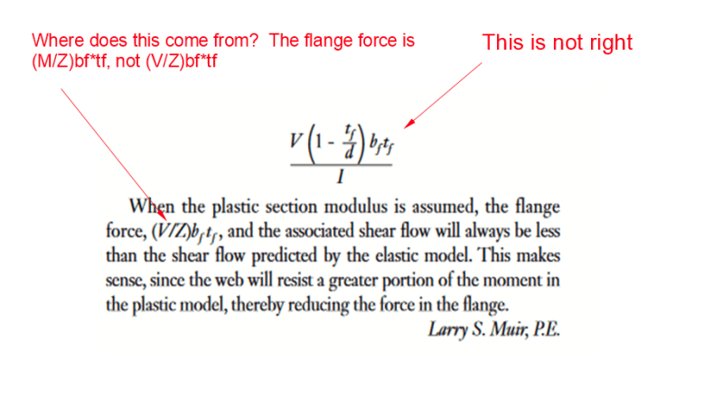
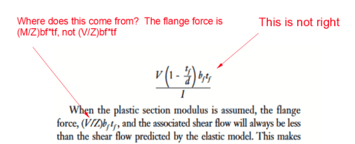
Anyone could please explain the principle shown on above screenshot.
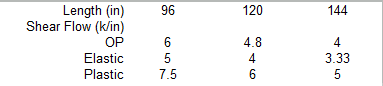
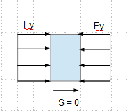
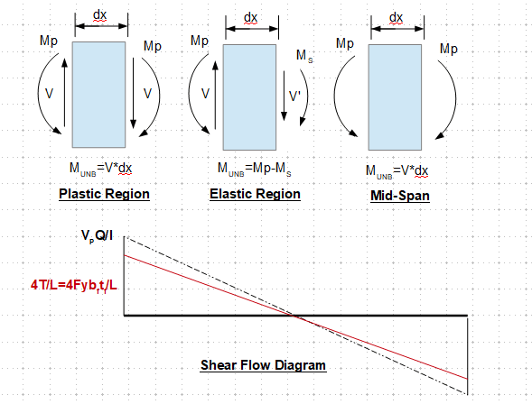
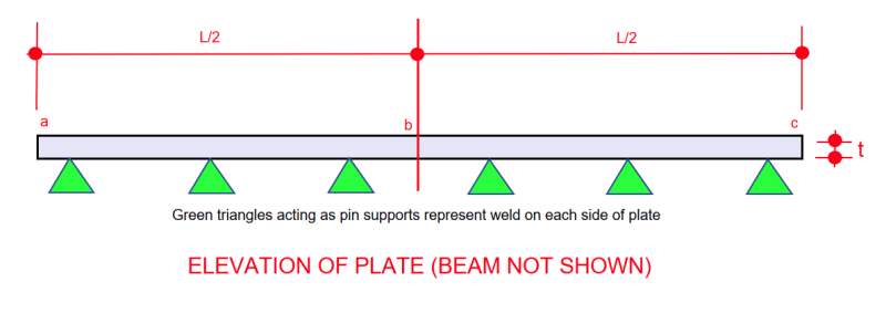
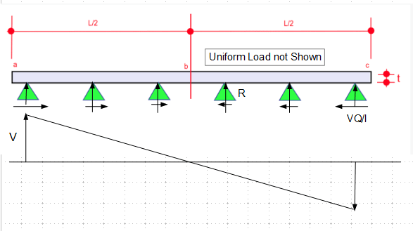
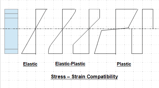
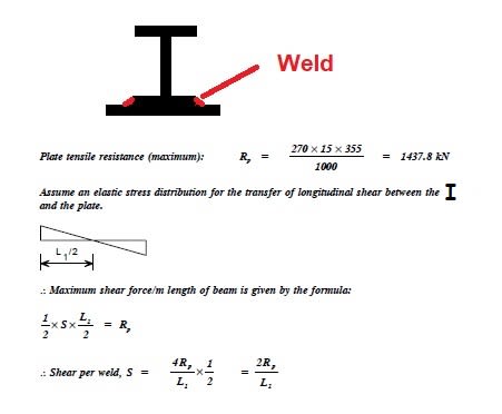
I'd like to understand the relationship between the maximum longitudinal shear and maximum plate tensile resistance when assumed elastic distribution stress.
Thanks for your help.

Best Regards,
JPMF
 
Replies continue below

Recommended for you

I'm still trying to figure out Ingenuity's post from yesterday. When the plastic modulus is assumed, the flange force should be (M/Z)b[sub]f[/sub]t[sub]f[/sub], not as shown below. That is the total shear required from the weld at each end of the beam. For uniform load, the shear flow at the support is 4Z*Fy/L. For non uniform loads, it will depend on the load distribution. For example, for a single point load at midspan, shear flow at the support will be 2Z*Fy/L and will remain constant from support to midspan.

image_hx6ioy.png


BA
 
Since Mp/My = 1.5, but the result using the OP's method is only 20% higher than the elastic method, the weld is not designed to the ultimate capacity of the section. See comparison below.

image_ax50uv.png


Please double check this method, and make sure it is what you want to do.
 
According to the method used for derivation of shear flow equation, there should be no shear flow when the section has plasticized, as the normal stresses are balanced.

image_anhb36.png
 
BA,

image_zzsfaw.png


Your question on the (V/Z)b[sub]f[/sub]t[sub]f[/sub] maybe explained by - M = V*1" in the article.

Stl Excg said:
The shear flow can be derived by drawing the free body for a 1-in. segment of the beam and applying equal and opposite
shears at either end. The shear will produce a moment equal to the shear force multiplied by the 1-in. moment arm.

The another term should be VQ/I = V(d-t[sub]f[/sub])b[sub]f[/sub]t[sub]f[/sub]/2I = V(1-t[sub]f[/sub]/d)b[sub]f[/sub]t[sub]f[/sub]d/2I, assume the section is symmetrical about x-axis. This author was mixing orange with banana.
 
Diagram below shows the under design using OP's method, if the beam is expected to form plastic hinges. Note that the OP's method is in agreement with the steel exchange, F[sub]DGN[/sub] = V*1"/Z = M/Z = T*A[sub]f[/sub].

image_ps6x6l.png
 
Below is an elevation of the plate of thickness t under the beam. The beam is not shown. The green triangles are a diagrammatic way of showing weld on each side of the plate. They act as pin supports.

When the beam is under full load, it bends down, stretching the plate. At Point b, the stress is Fy (yield stress) as a result of bending of the built-up-beam. The factored force in the plate at point b is T = A*Fy where A is the area of plate. Stress at points a and c is zero, so T = 0. The welds each side of b must resist the tension at b. The pins left of b feel a horizontal force T = A*Fy pulling to the right. The welds right of b feel a horizontal force of T pulling to the left.

If the load is uniform, factored shear flow will vary from a maximum value S at a and c down to 0 at point b. Total shear between a and b = (S/2)*L/2 = SL/4 which must equal T. So S = 4T/L or S = 4A*Fy/L.

image_hkqwtx.png


BA
 
This is our difference. The plate will bend with the beam based on stress/strain compatibility. Also, unless the applied load is direct tension on the cover plate, the tension wouldn't be uniformly throughout.

image_bmnajv.png
 
retired13 said:
This is our difference. The plate will bend with the beam based on stress/strain compatibility. Also, unless the applied load is direct tension on the cover plate, the tension wouldn't be uniformly throughout.

Wrong! The plate will bend with the beam, so the strain will vary across the section, but when the built-up-beam reaches full yield, the cover plate is well beyond yield strain at all points, so the stress will be Fy throughout and the tension will be uniform.


BA
 
Wrong, for simply supported beam, you couldn't have a beam/cover plate completely yield throughout the beam span, no matter from the theory (failure when 3 hinges forming)/code/serviceability point of view. Are you now applying uniform moment instead? Why keep changing your loading condition? Do a simple calculation for Mp, and get the uniform load and support reaction that causing the plastic moment. At the support, T = C = M/lever arm = 0, at the mid-span, T = C = Mp/lever arm = Fb*Af.
 
Of course it doesn't yield throughout the beam span. Failure occurs in a uniformly loaded simple beam when just one plastic hinge forms at midspan. By then, the cover plate has reached full yield and its axial force is A*Fy at midspan.

BA
 
Now you are correct. For simply support beam, T[sub]max[/sub] at where moment is a maximum, so mid-span.

Not a perfect sketch, but this is what I meant "stress-strain compatibility", smooth line/curve without abrupt jumps

image_nc9mza.png
.
 
Status
Not open for further replies.
Back
Top