Continue to Site

Eng-Tips is the largest engineering community on the Internet

Intelligent Work Forums for Engineering Professionals

  • Congratulations KootK on being selected by the Eng-Tips community for having the most helpful posts in the forums last week. Way to Go!

LP Condensate to Condensate Header Feasibility Check.

Pavan Kumar

Chemical
Aug 27, 2019
333
Dear All,

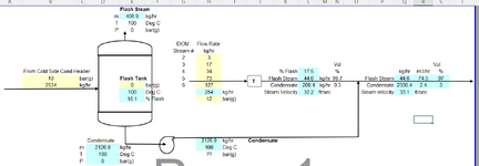
I have a process problem that I am trying solve. The Condensate from one side of the plant is sent to Flash Tank, flash steam separated by venting to atmosphere and the LP condensate is pumped to DN 50 (2"NPS) Condensate Header that has Condensate Flash Steam. The question is will the 2" Condensate header be overloaded resulting in high back pressure. This being done per Client's need who has asked as to check the feasibility. The input is provided below.

HP Condensate from Plant = 2534 kg/hr
Pressure upstream of Steam Traps = 10 bar(g)
Flash Tank Operating Pressure = 0 bar(g)

Condensate Header size = DN 50
Condensate Header Pressure = 0 bar(g)
Condensate Load = 254 kg/hr
Pressure upstream of Steam Traps = 12 bar(g)
1731705775622.png

My calculations are shown attached in the spreadsheet. The methodology I used (which I want to cross-check with you) is as follows:

1. Determine the % Flash in the 2" Condensate based on pressure reduction from, 12 bar(g) to 0 bar(g)
2. Estimate the Flash Steam Flow Rate and estimate the Flash Steam Velocity.
3. Estimate the % volume of Flash Steam and Condensate in the 2" pipe using the specific volumes of Flash Steam and Condensate.
4. Add the Condensate from Flash Tank and determine the new volume % of Flash Steam and Condensate.
5. Estimate the increase in the Condensate Liquid level and thereby estimate the reduced cross-sectional flow area for Flash Steam and thus the new Steam Velocity.
6. Check if this new steam velocity is still less than 15-20 m/sec recommended Flash Steam velocity in condensate return lines.

Your comments and resources will be helpful.

Thanks and Regards,
Pavan Kumar
 

Attachments

  • Plant Condensate to 2 inch Condensate Header.xlsx
    148.7 KB · Views: 7
Replies continue below

Recommended for you

HI,
A tool to support such calculations:
You need to supply a condensate pot with 2 separate lines, from there you can transfer the condensate to header via pump. Definitely more equipment is required. Is it worth to recover all the condensate?
Pierre
 
Last edited:
Your calcs so far cannot predict if the steam traps will be overloaded with high backpressure - calc stops at velocity estimate. Two phase flow pressure calcs can be complicated and risky especially in lines with risers. The calcs say that sizing case pressure downstream of existing steam traps is zero barg. Hence, if there are vertical risers in this 2phase condensate return line, it is very likely that this 2inch line is slugging some or all of the time, creating excessive backpressure on these existing IDOP traps.

See if there is ample excess capacity in each of these steam traps to deal with the backpressure induced at each trap from a 100% liquid full vertical riser ( line rising up to main pipe rack ? ) on this existing 2inch line going back to the central condensate collection drum ( de aerator ?). Do you have an overall piping isometric of this 2inch return header from these traps leading to central condensate collection ?
 
Assuming the condensate pump and trap discharges will ultimately discharge to an atmospheric tank, what is the pipe length downstream of the trap till the tank? The pressure drop in 2 phase flow may be significant
 
In your calculations you have assumed zero slip between the flash steam and the condensate flowing in the 2" pipe. It will not be like that. The condensate will flow at a slower velocity than the steam. Also, the condensate does not flow in a nice neat discrete layer at the bottom of the pipe. The steam will whip up the condensate and try to accelerate it and this is what makes the two phase pressure drop much higher than either of the two phases flowing alone.

The load, both in terms of flash steam and of condensate, is much higher for the 10 bar system than for the 12 bar system. Diverting the line after the 12 bar steam trap(s) into the flash vessel will not add much to the load on the flash vessel but it would mean that the pumped condensate would be liquid only and will give a velocity of around 0.3 m/s (1 ft/s) in a 2" line which should be OK unless the condensate line is extremely long.
 
Condensate Header Pressure = 0 bar(g)
It's incorrect to assume the pressure at the team trap outlet or the condensate return header is zero unless it's open to atmosphere. And, it won't work to connect the pumped condensate line to the steam trap header which may block the steam trap or cause water hammer in the actual operation.
 
Thanks Mr. Pierre. I will download the Measur tool and start using it.

Pavan
 
Your calcs so far cannot predict if the steam traps will be overloaded with high backpressure - calc stops at velocity estimate. Two phase flow pressure calcs can be complicated and risky especially in lines with risers. The calcs say that sizing case pressure downstream of existing steam traps is zero barg. Hence, if there are vertical risers in this 2phase condensate return line, it is very likely that this 2inch line is slugging some or all of the time, creating excessive backpressure on these existing IDOP traps.

See if there is ample excess capacity in each of these steam traps to deal with the backpressure induced at each trap from a 100% liquid full vertical riser ( line rising up to main pipe rack ? ) on this existing 2inch line going back to the central condensate collection drum ( de aerator ?). Do you have an overall piping isometric of this 2inch return header from these traps leading to central condensate collection ?
Hi George,

Yes there is 15 m riser after the steam traps in IDOM area, so the traps would have to sized for the back pressure of 1.5 bar(g) at then minimum. The steam from the steam mains comes down by 15m to the heat exchange equipment and the condensate from these traps goes through the riser to reach the 2" condensate return header. Yeah so there is 15m riser that the traps need to overcome the static head for. Lets say the traps have enough capacity ( we do not really know yet as the project is in Basic Engineering phase). Agree the condensate will have to be flashed to 1.5 bar(g) pressure instead of 0 bar(g) as I previously did. But this condensate will flash further once it reaches the 2" condensate return header where the pressure is close to o bar(g). You are right the condensate and flash steam will have to push condensate slugs after it reaches the 2" header. For this reason the trap discharge lines and the common condensate header have to be sized for bigger size correct?. I donot have the overall isometric of the 2" condensate header. I will provide more updates as I get them.

Thanks and Regards,
Pavan Kumar
 
Assuming the condensate pump and trap discharges will ultimately discharge to an atmospheric tank, what is the pipe length downstream of the trap till the tank? The pressure drop in 2 phase flow may be significant
Hi Mr. Goutam,

There could be significant pipe length for the LP condensate and 2" condensate header before it reaches the Deaerator where the Condensate from IDOM traps will be allowed to separate from the Flash Steam.

Thanks and Regards,
Pavan Kumar
 
In your calculations you have assumed zero slip between the flash steam and the condensate flowing in the 2" pipe. It will not be like that. The condensate will flow at a slower velocity than the steam. Also, the condensate does not flow in a nice neat discrete layer at the bottom of the pipe. The steam will whip up the condensate and try to accelerate it and this is what makes the two phase pressure drop much higher than either of the two phases flowing alone.

The load, both in terms of flash steam and of condensate, is much higher for the 10 bar system than for the 12 bar system. Diverting the line after the 12 bar steam trap(s) into the flash vessel will not add much to the load on the flash vessel but it would mean that the pumped condensate would be liquid only and will give a velocity of around 0.3 m/s (1 ft/s) in a 2" line which should be OK unless the condensate line is extremely long.
Hi katmar,

Agree with you fully. I am yet to know the reason why they want to push the pumped condensate into the 2" Condensate return line which will already encounter significant pressure drop due to two phase flow. I also did not understand why would any one want the Condensate to Flash in the Deaerator. It is better to separate the Flash Steam in a Flash Tank, condense the steam using a Vent Condenser and pump it along with the LP condensate back to the Deaerator in liquid form. There is a meeting with the client tomorrow and I will update you more.

Thanks and Regards,
Pavan Kumar
 
It's incorrect to assume the pressure at the team trap outlet or the condensate return header is zero unless it's open to atmosphere. And, it won't work to connect the pumped condensate line to the steam trap header which may block the steam trap or cause water hammer in the actual operation.
Hi mk3223,
If the trap discharge lines and the Condensate return header are sized for the low flash steam velocities of 15-20 m/sec and the traps are sized for the static head of 15m due to the riser will the traps still experience high back pressure causing them to fail or cause water hammer?.

Thanks and Regards,
Pavan Kumar
 
In most heat exchangers operating on steam, thermal duty modulation at each unit is by throttling the steam supply to the HX - this reduces the steam side pressure in the unit. All the steam trap does is to drain out the condensate when it is subcooled somewhat or when static differential across it exceeds a preset value. Hence, when any one unit is on low thermal duty demand, pressure upstream of the trap would be much lower than 10barg. The min steam side pressure will depend on the min thermal duty demand at these users. Hence a thermal rating check at each of these unit heat exchangers should be done at its known thermal duty turndown to determine the min pressure upstream of the trap.

Check also if you have the right type of trap for each IDOP user, which will depend on the type of process control used to modulate thermal duty.
 
If it is possible to connect the pump discharge point to the header at ground level then due to cooler pump discharge flow, the temperature of mixture will reduce after the connection and this may prevent flashing of steam in the vertical leg(15 m) and thereafter. This will greatly reduce the pressure drop which was possible due to the two-phase flow. The flow velocity will also be less (<0.5 m/s) and 2" header size may be adequate with this condition.

But as mentioned above the trap capacities need to be checked for higher back pressure.

However, after the traps up to the pump discharge connection, the header size should be increased to account for the two-phase flow.
 
f it is possible to connect the pump discharge point to the header at ground level then due to cooler pump discharge flow, the temperature of mixture will reduce after the connection and this may prevent flashing of steam in the vertical leg(15 m) and thereafter. This will greatly reduce the pressure drop which was possible due to the two-phase flow. The flow velocity will also be less (<0.5 m/s) and 2" header size may be adequate with this condition.

But as mentioned above the trap capacities need to be checked for higher back pressure.

However, after the traps up to the pump discharge connection, the header size should be increased to account for the two-phase flow.

Please ignore the quoted post. The header at 15 m needs to be pressurized to about 1.5 bar(a)(by a downstream CV) to prevent flashing. This increases the back pressure of traps. Trap supplier needs to confirm adequate flow at back pressure of about 2.5 bar(g), which may be possible with some trap suppliers.
 
If the trap discharge lines and the Condensate return header are sized for the low flash steam velocities of 15-20 m/sec and the traps are sized for the static head of 15m due to the riser will the traps still experience high back pressure causing them to fail or cause water hammer?.
Pavan,
In addition to the static head of 15m, do you consider the back pressure of the every branches on the 2" Condensate Header?
IMO, it's not realistic that the conditions of the pumped condensate head and the branches of the "traps" are to be the constant values through the whole Condensate Header.
 
If the trap discharge lines and the Condensate return header are sized for the low flash steam velocities of 15-20 m/sec and the traps are sized for the static head of 15m

Actually, the velocity will increase as the flow experiences pressure drop due to friction, which increases the amount of flash steam. Additionally, there is likely to be a critical(sonic) flow at the header exit.
 

Part and Inventory Search

Sponsor