Samkhp
Structural
- Oct 1, 2020
- 7
Hi guys,
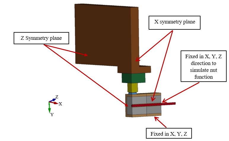
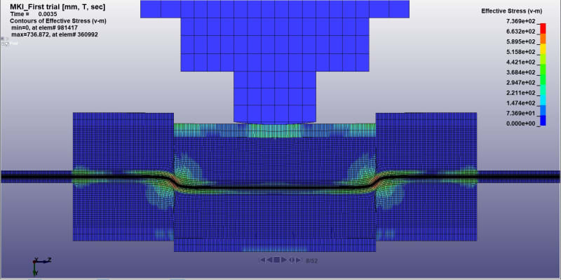
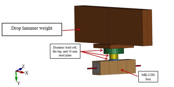
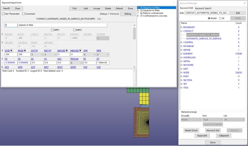
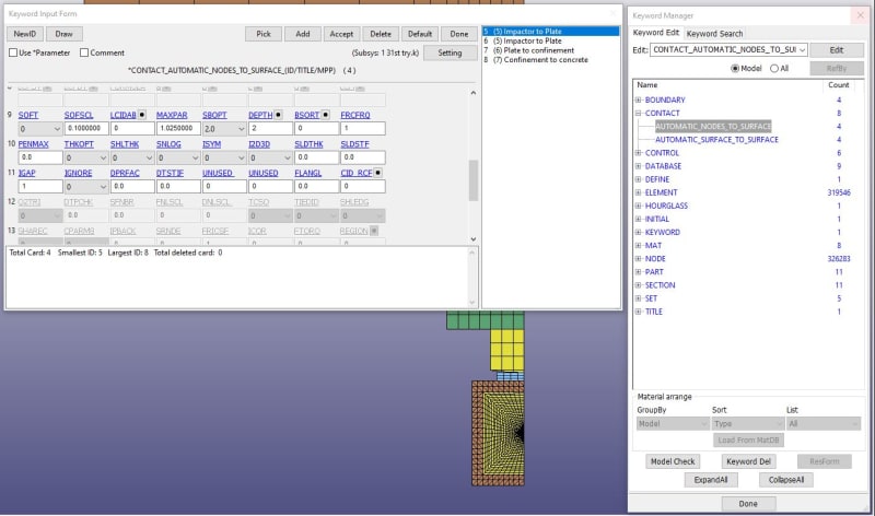
I am using Ansys/LS-Dyna to simulate behavior of a rock bolt jointed concrete
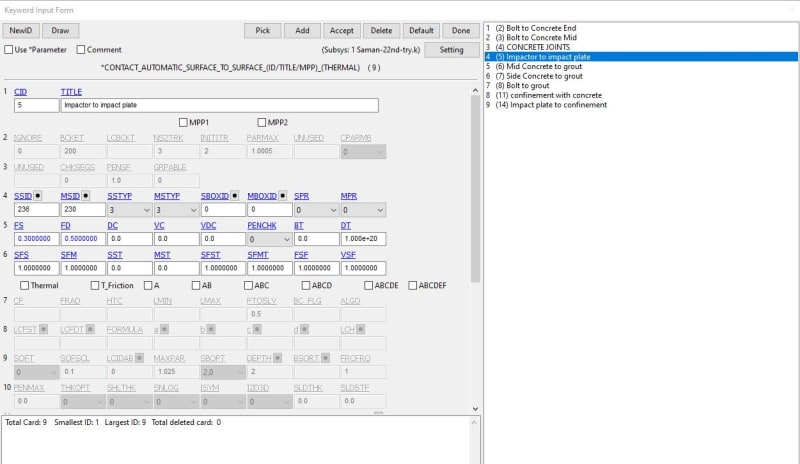
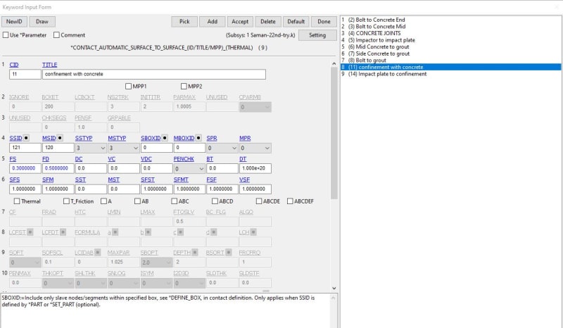
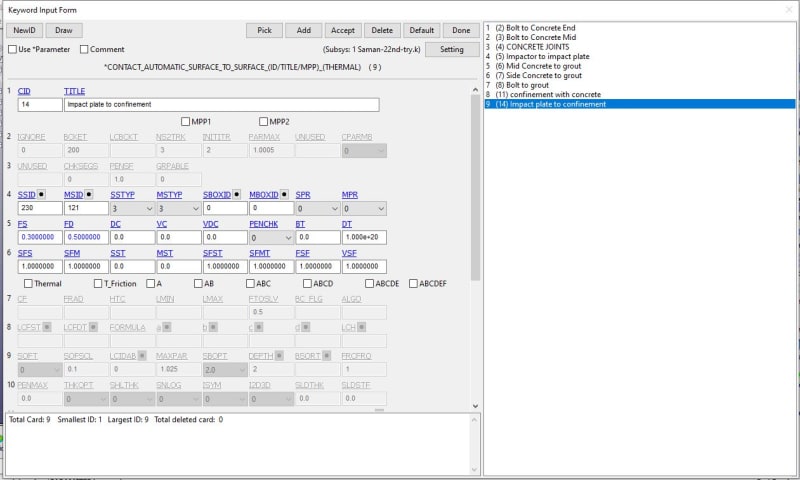
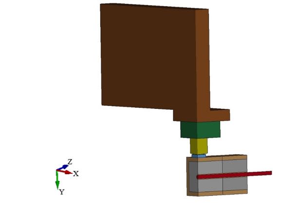 under impact load. I have attached a schematic of the model for your consideration. I have used rigid material for the impactor, MAT_159 for concrete and grout, MAT_24 for the rock bolt, MAT_003 for steel confinement wrapped around the concrete. I used Automatic_Surface_TO_Surface contact between each part as follows:
Concrete to concrete (Joint faces)
Grout to Rock bolt
Concrete to grout
Concrete to steel confinement
Steel confinement to Impactor
The geometry was imported through NASTRAN file built in strand7 software.
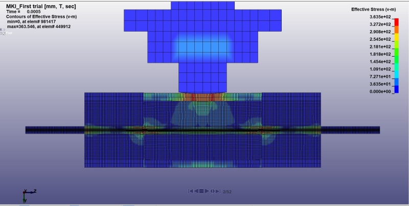
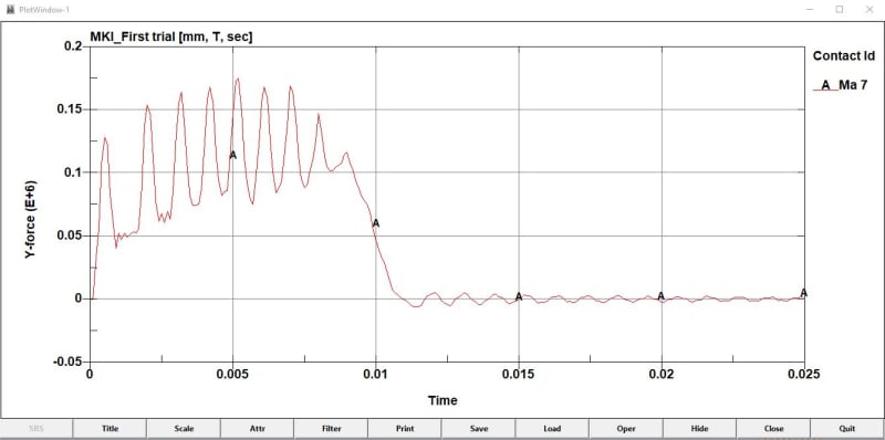
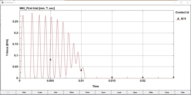
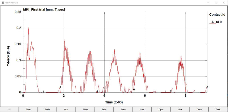
I have been running this model with no problem in terms of workability and getting results such as Total energy, internal energy and sliding energy and the results seem ok in comparison with the experimental results. However, the impact load vs time can not be driven and I have no idea why. I actually getting the impact results from the impactor to confinement as well as confinement to concrete contact but the results don't look fine. The results show some peaks which are basically due to the impact, and no load bearing is shown in the graph. What I mean is that when the impactor hit the steel confinement, I expected a compressive force to be implemented into the system but from the impact results this can't be seen. only some bounces can be captured. However, through confinement to concrete contact, the bounces are still there but there are some load bearing are seen.
I would be grateful if you could advise what the problem could be.
I am using Ansys/LS-Dyna to simulate behavior of a rock bolt jointed concrete
Concrete to concrete (Joint faces)
Grout to Rock bolt
Concrete to grout
Concrete to steel confinement
Steel confinement to Impactor
The geometry was imported through NASTRAN file built in strand7 software.
I have been running this model with no problem in terms of workability and getting results such as Total energy, internal energy and sliding energy and the results seem ok in comparison with the experimental results. However, the impact load vs time can not be driven and I have no idea why. I actually getting the impact results from the impactor to confinement as well as confinement to concrete contact but the results don't look fine. The results show some peaks which are basically due to the impact, and no load bearing is shown in the graph. What I mean is that when the impactor hit the steel confinement, I expected a compressive force to be implemented into the system but from the impact results this can't be seen. only some bounces can be captured. However, through confinement to concrete contact, the bounces are still there but there are some load bearing are seen.
I would be grateful if you could advise what the problem could be.