Continue to Site

Eng-Tips is the largest engineering community on the Internet

Intelligent Work Forums for Engineering Professionals

  • Congratulations KootK on being selected by the Eng-Tips community for having the most helpful posts in the forums last week. Way to Go!

Magnetic Center of 1MW motor 3

Status
Not open for further replies.

MacMcMacmac

Aerospace
Sep 8, 2010
56
20230524_093836_resized_yfxxjh.jpg


Good Day. We recently received our 1MW motor back from a re-bearing job. The DE bearing burnt up due to a lack of lubrication. It is a double spherical roller bearing that is lubricated through a port on a center groove machined into the periphery of the race. To me at least, it looked as though this bearing was insufficiently packed when it was overhauled last time in 2019. It had intermittent use since then. After investigating the failure, it seemed as though the grease port was also blocked, so it was a double whammy for that bearing. At any rate, we reinstalled the motor to a gearbox last week and were surprised to find our vibration monitor lighting up like a Christmas tree, with axial vibration being the highest. We had an outside expert come in to do some vibration analysis with some higher end gear than we had at our disposal, and he pointed to the gearbox as being the problem. Tear-down revealed nothing more than one worn thrust face. There was also some wear on the far side of the driven exhauster bearing. I am thinking that the motor may not have found its magnetic center before coupling up and there were severe thrust loads put into the gearbox causing the wiping of the thrust face.

Here is the kicker though. When the motor was installed, it became clear that during initial installation, there was so little clearance between the motor mounting holes and the bolts, that one bolt had to be machined in order to get it to pass through the hole. This severely limits the ability to set the motor in any position other than where it is. It has operated like this for decades, so I doubt this has caused the issue. The shafts were laser aligned with a PrufTeknic (sp) Rotalign and there was smiley faces all around.

The motor and gearbox are coupled by a large solid machined pair of hubs with 14 drive pins. The hubs are about 16" o.d., and complete with pins the whole assembly is estimated to be around 440lbs. We noticed that some replacement pins that were fabricated in house weight as much as 10grams less than the older pins. There were also 2 different types of lock nuts on the pins which varied by 5 grams. I do not think that these could be responsible for the vibration issues given the low speeds and weight of the hub. i would like to replace these with a grid coupling, since they are time consuming to link up. I am not sure how tolerant grid couplings are of thrust loads however. The balance condition of these hubs are also unknown. This is a mid 30s era machine, taken as war booty after the WWII. It was apparently installed at the the V2 works.

I noticed during the installation of the coupling drive pins that I was able to insert a large pry bar between the face of the drive and driven hub and move the rotor about 5/16" of an inch axially away from the D.E.. This seems excessive to me. The axial travel of the rotor away from the drive end seems constrained by the D.E. bearing bottoming out in its housing, but the axial travel towards the D.E. seems to be constrained by nothing bu the pins, or the hub faces, which is to say, the inward travel of the N.D.E. bearing has not bottomed out in its housing. i hope that is not too confusing.

The motor was converted from sleeve bearings to roller bearings in about the mid 90s. On the new end covers, the end caps of the bearing housings have an inner lip or "spigot" that I assumed set the position of the bearings, and hence, the shaft in the motor. Upon further inspection, the NDE bearing race of the identical second stage exhauster motor in the train had a gap of about 1/8" of an inch to the raised spigot ring, while the NDE bearing of the repaired motor had a gap of about 1 3/4" between the bearing race and the spigot ring. I honestly don't see what if anything is keeping this rotor from walking axially. The bearings are secured to the shaft with a locking nut and lock washer, and when the rotor is moved manually the whole bearing slides inside the end cover. The repair shop said if the bearing O.D. is on the small side of tolerance, it can have enough give to move in the case. I do not have the expertise to contradict this, but even in small motors there is usually a wave washer of some kind to help keep the rotor where it needs to be.

I have read in another post that motor tend to want to have some thrust into the driven machine, and that if there is not, it can oscillate around magnetic center. This seems somewhat plausible given the symptoms. I cannot think of another reason for high axial vibes. The motor was run uncoupled after the vibration run, and signatures jibed with what the repair shop had taken before shipment. Balancing the rotor was also done as part of the repair.

 
Replies continue below

Recommended for you

Spherical roller bearings are locating bearings which do not allow the rotor to move axially as long as their outer races are gripped tightly by the bearing end caps. I assume NDE bearing is a roller bearing, which is non-locating and allows thermal expansion of the shaft.

Post the photos of both side bearing housings & bearings taken during assembly of the motor.


Muthu
 
Magnetic center is not going to be an explanation of anything here. It is a small force for one thing. And more importantly you have converted to rolling bearings which will limit axial movement of the rotor.

I think axial allowances / forces will be the big story as edison mentioned.

When you had sleeve bearings, the gearbox controlled position of the shaft and the motor shaft floated axially accordingly.

When you put rolling bearings in, you defeated that.

The worn thrust face is a clue that the gearbox bearing was axially loaded against something, most likely against a motor bearing.

Info about the end play movement afforded in both machines would be part of the picture as edison asked about (along with estimates of thermal growth).

But also, the type of coupling plays a role in the picture now. What type of coupling is it?
[ul]
[li]If it's a rigid coupling, that's a big problem. Grid coupling you mentioned would be better although there are lots of flexible coupling options to look at[/li]
[li]If it's a pin and bush coupling where the two halves can move axially relative to one another, then inspect it carefully to see if anything is preventing the intended motion. Like if the two hub faces are in contact with each other, that would defeat the ability to slide any further.[/li]
[/ul]


The gear is on sleeve bearings with ODE pretty much axially locked both ways on the journal shoulders. Not clear about gear DE bearing axial play but it does not matter since the gear shaft is locked on NDE.

With the correctly installed spherical double row bearing, the motor rotor should not move axially. If the motor rotor is moving axially for whatever reason, only thing I could think of is that the motor DE spherical double row bearing is not axially held in place by the DE bearing end caps and the whole bearing is sliding along the bearing housing on its OD. I could be wrong.

Muthu
 
> Quote (I was able to insert a large pry bar between the face of the drive and driven hub and move the rotor about 5/16" of an inch axially away from the D.E.)

I missed that. I'm going to assume you have a pin and bush coupling. Was there a gap to insert the prybar (there should have been). If not and if the two faces are in contact, that would defeat the sliding function of the pin and bush coupling which could allow gearbox thrust to load the motor bearing (assuming gearbox thrust bearing doesn't limit it first)
 
Hello again. Thank you for your replies. The explanation of the centering forces will let us eliminate that as a cause.

The couplings are pin and bush. There is a bare end that passes into a closely fitted bore. The other end is in a very loosely fitted bore which then has a metal sleeve with a rubber bushing in it installed over the pin. The pins are kept from floating out by heavy washers and lock nuts on either end.

These pins have been an issue. Over the years, various methods and amounts of force have been required to get them into position. Some go in by hand, others are tight and need persuasion, either with hammer taps with a brass drift, or an enerpak. Some were so disfigured on the end threads that we had to make 6 new ones. They installed ok, but after the run, they took quite a lot of force to remove. Way too much. They were dimensionally identical to the old pins, but were made from plain 1025 or the like, and were somewhat lighter than the originals. It is entirely possible these new ones bound up in the coupling and did not allow for any freedom of movement. We sent them back to the shop to have an extra thou or two taken off the o.d. and they reinstalled fine.

20230331_110724_taipdr.jpg


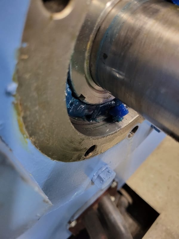
This is the detail of the D.E. of the motor with the failed bearing. This is actually the bearing in question. As you can see, there is a locating piece behind the bearing cap which positions this bearing in place. This piece was able to be slid out by hand and I inspected the failed D.E. bearing directly behind it. The gap to the face of the piece, and the bearing end cover spigot seem to be locating this bearing in place.

20230523_142102_resized_tsennn.jpg


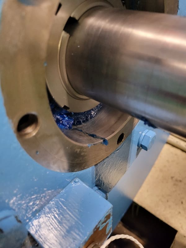
This is the detail of the N.D.E. bearing on the second stage motor which did not fail. As you can see, the bearing race is quite close to the end cover face. The bearing cap has a locating ring on the inside face. You can just see a tide mark between the bearing face and the spigot ring, which is about 1/8" of clearance. This seem reasonable to me to allow this bearing to move outward as the motor heats up in use.

20230523_142133_resized_1_l2ifhk.jpg


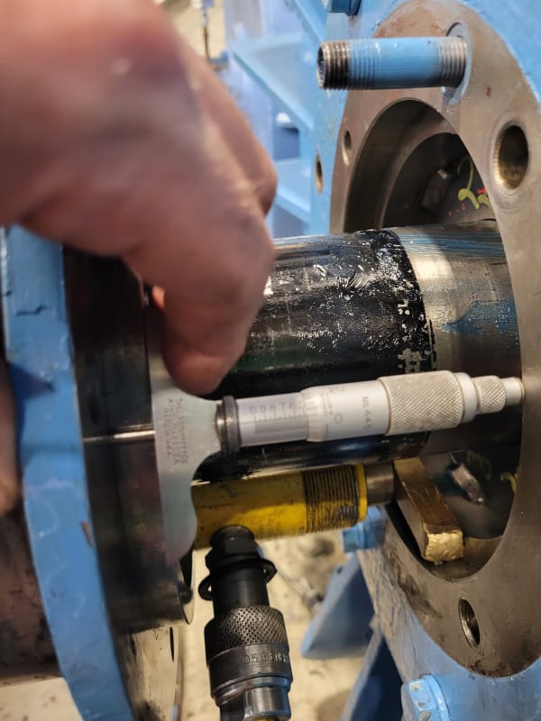
This is the N.D.E. bearing of the motor which experienced the bearing failure. The gap between the bearing race and the end cover is about 1 3/4". The spigot ring on this end cover only goes into the bore about 1/2", so there is no way on earth it will limit any travel of the rotor. I can physically move the motor rotor with a pry bar and this whole N.D.E. bearing will move in and out about 5/16". It does not seem correct.
 
I may not have all the details but with the damage of the gearbox thrust bearing and motor bearing it seems likely the gearbox bearing and motor bearing are loading each other.

You've already identified two problems with the pin and bush coupling, either one of which could explain why the coupling halves are not sliding relative to each other to prevent that type of loading:
[ul]
[li]1 - You said the pins get stuck. That could prevent the coupling halves from sliding relative to each other.[/li]
[li]2 - You said the hub faces were touching each other. That shouldn't happen and can prevent the coupling halves from sliding relative to each other. This one seems a bit more likely given the as-found condition was indeed in contact.[/li]
[/ul]
To correct the 2nd condition, you'd need to change something to make sure the coupling stays in its working range as you move the gearbox anywhere within its endplay. That may involve moving the hubs back further on their shafts, moving the machines, or....

Now I'm thinking about something else you said. You said you could move the gearbox shaft by 5/16" That sounds very high for gearobx thrust clearance. Do you know thrust clearance spec for the gearbox? I'm going to assume the gearbox thrust clearance is supposed to be a lot smaller, something like 1/16" or 1/32". And I'll also assume the machine was set up properly at some point in the past including the coupling limited to within its proper range. Then maybe what went wrong since then was the gearbox clearance opened up somehow, allowing the gearbox shaft to move too far towards the motor allowing contact between those hub faces. But how does gearbox clearance open up that much (like 5/16"-1/16"=1/4"). Most babbit is not more than 1/8" thick or so. Whatever it is, if that gearbox thrust clearance is too high you've got to figure out why. EDIT - maybe the hub was moving on the shaft and it was just hub but not shaft moving by 5/16"?


Excess thrust in the gear box.
Excess clearance on the NDE bearing.
DE bearing locked in place.
Have you checked that the DE bearing is locked in the correct location on the shaft?
Is the wear mark on the thrust bearing in a direction to support this possibility?

--------------------
Ohm's law
Not just a good idea;
It's the LAW!
 
> Excess thrust in the gear box.

The thrust associated with transmitting torque in the single helical gear should be seen by the gearbox thrust bearing and should not transmit to the motor if the pin and bush coupling is functioning right.

> Excess clearance on the NDE bearing.
> DE bearing locked in place.

It sounded like that is the intended configuration.. fixed DE floating NDE.

Deleted above. Sorry Bill I first thought you were suggesting causes. Now I realize you were repeating facts.

===== === ===

I'd like to talk about pin and bush couplings some more. Here is a smaller pin and bush coupling The two halves do not bolt together, the nuts just fasten the pins to one hub and those pins stick through a hole (bush) in the other hub so they can transmit torque but they can't transmit any thrust (the pins would slide axially in the hole before transmitting any thrust). So if they're set up right (hub faces not able to contact, pins don't stick) they should prevent any external thrust load being applied to the motor.

That's a small pin and bush coupling in my link above, way smaller then what would go on a 1 MW application. It does have rubber parts which I understand would accommodate misalignment. For op, does your coupling incorporate any flexible parts on the pin or wear material like a bronze sleeve inside the hole? I've never seen one that big, but I think most of these couplings have one or the other.

Also curious if I was standing beyond the NDE of the motor looking toward the gearbox would it be rotating CCW? If so then the gearbox thrust pushes toward the motor. Is the thrust face that wore the same thrust face that limits gear motion toward the motor?
 
Did I read this correctly?
1> The good motor has about 1/8 inch clearance at the NDE.
The problem motor has over 1 inch clearance at the NDE.
If a wrongly located bearing is holding the rotor 1 inch away from the proper location, it may well have pushed the coupling pins further into the holes. This may be causing the pins to bind.
Check the location of the DE bearing on the shaft.
If possible check that the rotor is centered in the stator.

--------------------
Ohm's law
Not just a good idea;
It's the LAW!
 
Yeah good point Bill, those are some weird large differences.

> I can physically move the motor rotor with a pry bar and this whole N.D.E. bearing will move in and out about 5/16". It does not seem correct.

Since the bearing is interference mounted to the shaft, are you saying the whole rotor is able to move 5/16"? Or something else?
 
I suspect that the bearing may have been installed up against a shoulder.
But;
OP said:
The motor was converted from sleeve bearings to roller bearings in about the mid 90s.
The bearings were originally sleeve bearings.
A shoulder to locate a sleeve bearing on a shaft will not be the correct locator for a spherical bearing.
Normally, when there is a shoulder on the shaft, the bearing is pressed up tight to the shoulder.
Tight against the shoulder is probably the wrong location for the newer spherical bearing.
Have I suggested this before?
Check the location of the DE bearing on the shaft.
Heck, check both bearing locations. The NDE bearing may also be out of position enough to cause problems.

--------------------
Ohm's law
Not just a good idea;
It's the LAW!
 
Sorry for the repetition but in my defence, I once took a course in instruction methods.
It was pointed out that important information should be repeated three times.

--------------------
Ohm's law
Not just a good idea;
It's the LAW!
 
Thank you everyone. First let me clarify a mistake I have made. The shaft end clearances are about 5/16", the total end float of the rotor is about .110". This is still in sharp contrast to the second motor coupler which exhibits zero float in the exact same configuration. I cannot move that rotor at all.

After calling in some expertise from a large millwright/electric motor/generator repair facility south of the city, we have come up with following plan of action:

Drive the shaft into the motor as far as it will travel so the D.E. bearing is fully seated into its bore. Remove the end cover and distance piece, and measure the distance from the motor end face. Add the distance piece length and end cover spigot together and make and install a split ring to take up the excess clearance, minus a few thou to prevent crushing against the bearing race when it is closed up. This will fix the D.E. bearing in place and leave the NDE bearing to float for thermal growth.

While the distance piece is out, we can check for something weird like a loose lock nut. I doubt this, but never say never. The fact that I can easily move the shaft shows me something is wrong in the d.e.. Either the shaft is slipping through the bearing, or the bearing is sliding inside the motor end cover. Either way it has to be corrected and fixed in place.

For the gearbox input shaft thrust bearing, the thrust ring has worn a circular path on the babbitt face of about .010" to .020" deep. The proposed method to deal with this is to machine the face flat again, and shim the entire steel bearing housing forward to take up the slack. There are removable brass pads with shims on them on the outside faces of the housing that can allow the bearing to be positioned within the groove in the case it sits in.There is still a good thick layer of babbitt on the thrust face, with no cracks or delamination evident. I opined that the bearing carrier looked symmetrical and perhaps we could just turn it around and use the undamaged rear thrust face, but we all agreed that was a bit too back woods engineering without proper drawings and too big of a chance to take. If the steps we take can solve the issue and get us back within acceptable vibration limits, it will be a win for now. Once we have a more open schedule we can get these bearings rebuilt.

The motor guys were a bit lukewarm on the grid coupler. They suggested a twin disc arrangement. We agreed that tight drive pins may be an important component of the problem. The couplers have been doing their thing for 90 years now though, so its probably more of a problem of setup than of the technology itself.
 
So the motor DE locating bearing was not properly located in the housing just as I suspected?

A correctly sized split ring (axial clearance + one thou) that will press the DE bearing outer race positively by one thou from the front end is needed. And the coupling bolts should have that extra bit of length since the coupling will now move away from the original position by whatever the axial movement you measure.

This is a job that should have been done by that repair shop who changed out the bearings.

edit:

This is assuming the bearing is a tight fit on the shaft. If it is loose on the shaft, you got a bigger problem.


Muthu
 
MacMcMacmac said:
Drive the shaft into the motor as far as it will travel so the D.E. bearing is fully seated into its bore.
I think you're suggesting the bearing needs to be driven further in on the shaft against a shoulder in an attempt to reduce endplay. The large motor endplay is unusual and certainly could be an indicator of something wrong in the setup of the motor, but I don't see the endplay itself is necessarily the problem that would cause external loading of motor bearings as long as the range of motion allows the motor rotor to move far enough away from the gearbox to avoid being loaded by the gearbox, and the bearing doesn't get stuck in its housing.

So the bigger question is can the motor move far enough away from the gearbox to avoid loading. If the motor DE bearing is the one that limits motion away from the gearbox, then the motor DE bearing would have to be moved further out on the shaft (not further in) in order to eliminate motor loading by the gearbox. And the differences you reported on the NDE also suggest the rotor would have to move further away from the gearbox to match the other motor, which again would seem to suggest the DE bearing would have to be moved further out (not in) on the shaft.

Of course in a "normal" motor you have steps in the shaft and you know the bearing is correctly positioned when you push the bearing all the way in against the step. But here the symptoms suggest the bearing is currently positioned too far in. So I dunno, either we're missing something or maybe this is not a normal motor in that respect (maybe there are no shaft steps to assist with correctly positioning the bearing in this motor).

EDIT2 - I guess we might come up with a scenario where no movement of the bearing on the shaft is required to correct the condition. That scenario would be that the spacer outside the DE was simply too small which allowed the shaft to float too far toward the gearbox, which is I think what edison suggests. I agree fixing a spacer seems like a simpler logical thing to try before going into an oddball exercize trying to move a bearing on the shaft. But that scenario of DE spacer too small wouldn't load the bearing unless we also postulate the bearing got stuck in the housing after the rotor floated toward the gearbox. That seems unlikely to me since axial force and vibration can usually move a bearing in a housing (it's a principle relied on heavily in motor design). But then again none of the scenarios really seem to explain everything well. Maybe something caused intermittent sticking in the housing explains why the numbers seem to be changing.

EDIT3 - 2 different scenaros both unlikely. 1 - spacer too small and bearing stuck in housing. 2 - no shaft steps and bearing inserted to far in. So to distinguish between the two scenarios I'd check the spare motor and if the spacer is larger there that would tend to support the scenario that the spacer is the root problem and there's no mispositioniong of bearing too far in on shaft. If there is no mismatch in spacer size then maybe try to check shaft extension measurements to see if it supports bearing too far in on the shaft.


MacMcMacmac said:
I noticed during the installation of the coupling drive pins that I was able to insert a large pry bar between the face of the drive and driven hub and move the rotor about 5/16" of an inch axially away from the D.E.
Is that still a correct fact? (that's a lot more than 0.11" from motor... leaves something like 0.2" movement for the gearbox which is still a lot... or else the motor endplay is more than 0.11).


MacMcMacmac said:
For the gearbox input shaft thrust bearing, the thrust ring has worn a circular path on the babbitt face of about .010" to .020" deep.
Which side is worn? The side that prevents gearbox movement toward the motor, or the side that prevents movement away from the motor? (To my thinking if it's the side that prevents movement away from the motor then that would be consistent with problem originating soley in motor positioning, but if it is the side that prevents movement toward the motor then that's a muddier picture.)


EDIT1 - I'll throw out a few less important brainstorming ideas that are not as directly relevant, but just wanted to widen the net because it seems we might be missing something somewhere:
* is it possible the DE endbell is not fully seated onto the stator frame (maybe something stuck between them)? I've never heard of that but I'm looking for alternatives to the theory that the DE bearing was inserted too far which would also be quite odd considering normal stepped shaft construction would prevent that.
* still waiting for an answer on: "if I was standing beyond the NDE of the motor looking toward the gearbox would it be rotating CCW?"
* I read the big differences you described on the ODE but I couldn't visually discern the difference in the photos.
* From a distance, I'd be uneasy moving a bearing without fully understanding the bearing setup, which would require assistance from someone that knows the motor or pulling the motor apart. That's just my thought, you know the situation better than me.
 
Remember, the original sleeve bearing was replaced with a spherical bearing.
It is highly unlikely that the spherical bearing is as wide as was the original sleeve bearing.
If the new bearing was pushed up against the shoulder, it is probably in the wrong location.
Likewise the NDE bearing is most likely in the wrong position.
I would compare the locations of both DE and NDE bearings to the good motor.
You may inquire of the shop if there were a couple of spacers left over.

--------------------
Ohm's law
Not just a good idea;
It's the LAW!
 
I took awhile to get there but my final edit (edit3) also suggested a comparison between the two motors to distinguish between two competing scenarios. That's something similar to what Bill suggested, but he didn't need as much rambling to get there.
 
20230525_091422_wgzrrz.jpg


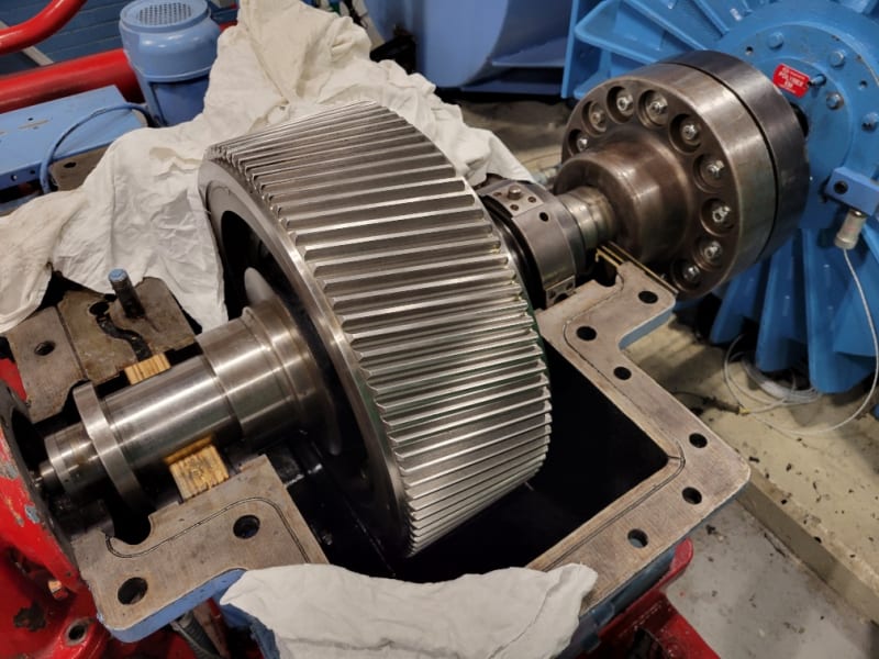
I removed the front cover, pulled the couplings together to get the spacer ring out far enough to pull out by hand to measure the o.d., then I reinstalled it and bottomed out the ring and bearing in its bore with an Enerpac, until I just felt resistance in the lever. This is probably a more accurate and consistent method than a pry bar.

The end cover face to the spacer ring face distance was 0.715". The spigot ring is 0.453", so there is around .250"-.260" of float in the d.e. bearing. I am giving a range since I doubt the ring was sitting completely flush all around. Sorry for all of the conflicting measurements, but this is really the first methodical approach to seating this bearing.

I watched as I moved the shaft with the pry bar, and the bearing and locking ring are firmly attached and moving with the shaft. So, it seems we need to manufacture a spacer for this end to take up the slack while leaving a bit of room to avoid putting any crush on the race. This leaves me with a couple of questions;
1) Has this bearing always had this much play?
2) Is it now only evident because we happened to hit on a bearing on the low end of it's o.d. tolerance, and most importantly,
3) Does this affect the alignment of the outer bearing lubrication groove with the grease port in the end cover? This is a biggie, since lubrication failure of this bearing started this whole mess. It could not have happened at a worse time, as we are on the cusp of a very important test.

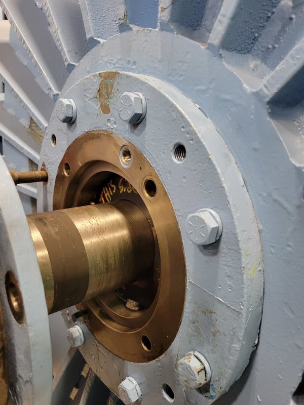
As for rotation, if you look at the motor in the first picture, it would be turning clockwise on the d.e..

The wear on the thrust bearing is on the face towards the motor, so it is as if there was significant thrust being imparted to the gearbox from the motor.

The shaft end gap has now increased appreciably as you might well imagine. We will have to approach the pin installation very carefully. There is a chance of applying high clamping loads on the hubs if we run out of clearance before the nuts have bottomed out on the threaded ends. Some of the heavy washers on the pin ends are heavily dished, so this may have been an issue in the past.

We have to eliminate the assembly stresses from tight pins as well. I am wondering how much this machine might have been has been fighting its own setup.

Feel free to critique my methodology and proposed solutions.

Thanks!
 
Are you able to run the motor uncoupled with the bearings unrestrained to see where it finds its own magnetic center?
The DE bearing should be locked on the shaft and in the housing and should properly locate the rotor in the stator.
The NDE bearing should be free to move in the housing to accommodate thermal expansion of the shaft.
The coupling pins should allow for any slight thermal expansion of the external shafts.


--------------------
Ohm's law
Not just a good idea;
It's the LAW!
 
Status
Not open for further replies.

Part and Inventory Search

Sponsor