Eng-Tips is the largest engineering community on the Internet

Intelligent Work Forums for Engineering Professionals

Magnetic Center of 1MW motor 3

Status
Not open for further replies.

MacMcMacmac

Aerospace
Sep 8, 2010
56
1
0
CA
20230524_093836_resized_yfxxjh.jpg


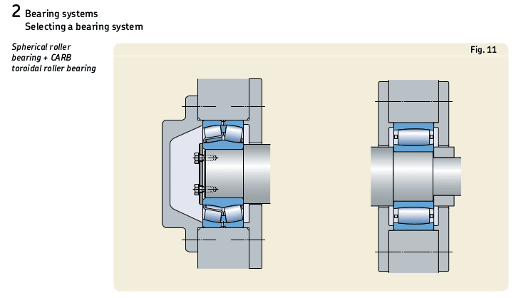
Good Day. We recently received our 1MW motor back from a re-bearing job. The DE bearing burnt up due to a lack of lubrication. It is a double spherical roller bearing that is lubricated through a port on a center groove machined into the periphery of the race. To me at least, it looked as though this bearing was insufficiently packed when it was overhauled last time in 2019. It had intermittent use since then. After investigating the failure, it seemed as though the grease port was also blocked, so it was a double whammy for that bearing. At any rate, we reinstalled the motor to a gearbox last week and were surprised to find our vibration monitor lighting up like a Christmas tree, with axial vibration being the highest. We had an outside expert come in to do some vibration analysis with some higher end gear than we had at our disposal, and he pointed to the gearbox as being the problem. Tear-down revealed nothing more than one worn thrust face. There was also some wear on the far side of the driven exhauster bearing. I am thinking that the motor may not have found its magnetic center before coupling up and there were severe thrust loads put into the gearbox causing the wiping of the thrust face.

Here is the kicker though. When the motor was installed, it became clear that during initial installation, there was so little clearance between the motor mounting holes and the bolts, that one bolt had to be machined in order to get it to pass through the hole. This severely limits the ability to set the motor in any position other than where it is. It has operated like this for decades, so I doubt this has caused the issue. The shafts were laser aligned with a PrufTeknic (sp) Rotalign and there was smiley faces all around.

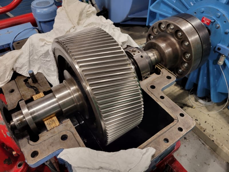
The motor and gearbox are coupled by a large solid machined pair of hubs with 14 drive pins. The hubs are about 16" o.d., and complete with pins the whole assembly is estimated to be around 440lbs. We noticed that some replacement pins that were fabricated in house weight as much as 10grams less than the older pins. There were also 2 different types of lock nuts on the pins which varied by 5 grams. I do not think that these could be responsible for the vibration issues given the low speeds and weight of the hub. i would like to replace these with a grid coupling, since they are time consuming to link up. I am not sure how tolerant grid couplings are of thrust loads however. The balance condition of these hubs are also unknown. This is a mid 30s era machine, taken as war booty after the WWII. It was apparently installed at the the V2 works.

I noticed during the installation of the coupling drive pins that I was able to insert a large pry bar between the face of the drive and driven hub and move the rotor about 5/16" of an inch axially away from the D.E.. This seems excessive to me. The axial travel of the rotor away from the drive end seems constrained by the D.E. bearing bottoming out in its housing, but the axial travel towards the D.E. seems to be constrained by nothing bu the pins, or the hub faces, which is to say, the inward travel of the N.D.E. bearing has not bottomed out in its housing. i hope that is not too confusing.

The motor was converted from sleeve bearings to roller bearings in about the mid 90s. On the new end covers, the end caps of the bearing housings have an inner lip or "spigot" that I assumed set the position of the bearings, and hence, the shaft in the motor. Upon further inspection, the NDE bearing race of the identical second stage exhauster motor in the train had a gap of about 1/8" of an inch to the raised spigot ring, while the NDE bearing of the repaired motor had a gap of about 1 3/4" between the bearing race and the spigot ring. I honestly don't see what if anything is keeping this rotor from walking axially. The bearings are secured to the shaft with a locking nut and lock washer, and when the rotor is moved manually the whole bearing slides inside the end cover. The repair shop said if the bearing O.D. is on the small side of tolerance, it can have enough give to move in the case. I do not have the expertise to contradict this, but even in small motors there is usually a wave washer of some kind to help keep the rotor where it needs to be.

I have read in another post that motor tend to want to have some thrust into the driven machine, and that if there is not, it can oscillate around magnetic center. This seems somewhat plausible given the symptoms. I cannot think of another reason for high axial vibes. The motor was run uncoupled after the vibration run, and signatures jibed with what the repair shop had taken before shipment. Balancing the rotor was also done as part of the repair.

 
Replies continue below

Recommended for you


Yup, that's your problem.


Once the DE bearing with rotor is pushed all the way back to the bearing housing end, are you able to see the central greasing groove on the bearing OD via the greasing port? If not, you need to dismantle the motor and recenter the DE bearing to match the bearing greasing groove with the greasing port on the housing and then do required corrections to both the shaft and housing to ensure a hard press fit of the bearing OD. Touchyfeely axial press fit on the bearing OD isn't going to cut it.

As I said, the repair shop did a poor job of checking these things.

Muthu
 
I removed the front cover, pulled the couplings together to get the spacer ring out far enough to pull out by hand to measure the o.d., then I reinstalled it and bottomed out the ring and bearing in its bore with an Enerpac, until I just felt resistance in the lever. This is probably a more accurate and consistent method than a pry bar.
Oh, so that’s what you meant by drive the bearing into its bore! Sorry I completely misunderstood and rambled quite a bit about what I thought was your plan to move the bearing on the shaft. Never mind. My apologies.


As for rotation, if you look at the motor in the first picture, it would be turning clockwise on the d.e..
Thanks. That makes the gearbox thrust toward the motor.

The wear on the thrust bearing is on the face towards the motor, so it is as if there was significant thrust being imparted to the gearbox from the motor.
Ok, so that does not support a scenario where the motor bearing was fighting the gearbox bearing which was my earliest thought. Now it’s not as clear what relationship the gbx thrustface wear has to the other symptoms. Gearbox thrustface wear may have been one contributor towards allowing gearbox shaft to move toward the motor, but it’s only 0.01-0.02” wear and the measured motor endplay should allow it to float to compensate, so it's no longer clear how related are these two observations (axial motor vibration and gearbox thrust face damage).

I guess there are 2 different scenarios to explain the gbx thrust face wear. The more benign scenario (and more likely imo) is it existed for long-term operation since before the motor swap. The more alarming scenario would be that it occurred since motor swap since that would mean a very high rate of wear which we can’t blame it on the motor (the motor can’t load that particular face)…. so that would mean there is some undiagnosed/uncorrected problem that created the gearbox wear in a very short period of time.
 
I would have expected the motor end play to be equal to or only slightly more than the internal clearance of the spherical roller bearing, the mounting of this bearing should provide very little end play of the outer race. Thermal growth of the motor should be taken care of by the plane roller bearing.
Your motor bearing arrangement arrangement is similar to this one.
Screenshot_from_2023-05-25_20-43-54_ffuhrr.png

Picture from SKF motor handbook available from here
 
I agree. I see no reason to have as much float in this shaft, even though the motor overhaul shop says it is nothing to worry about.

It looks like this motor is going to be sent out again to have the work inspected.

I also agree that the babbitt bearing wear is something that has probably existed for quite awhile. The second shop concurred.

The fact that the uncoupled motor vibes seemed to match the shop's recorded measurements before shipping, combined with the fact that the new pins seemed to bind up strongly in the coupling now makes me suspicious that the fault may have been the pins all along, binding and unbinding as the coupling spun, playing up the end float issues. The old pins were no models of accuracy however, with a .003" lack of concentricity from large end to small end on some. We are having a complete new set of pins made up at our machine shop. I see a long and tedious hand fitting and balancing of the new pins in the near future. The guys from the millwright shop said they recently had a 1500hp pump motor at the city water purification plant fail to synchronise due to the drive pins being so bound up in the coupling the motor was pulling excess amps and tripping out before it could get up to speed.

The bearing on the right on the above picture is how the current d.e. bearing sits in the end cover of the motor, with a spacer ring
and a retainer cap on front and back, except it is a spherical roller bearing of course. Instead of being captured in place, it has this extra float. It is a tapered bore bearing sitting on a sleeve with a lock nut.


Wait, what? It requires special set of tools for mounting and dismounting and internal clearance measurement etc.

Wonder that's why the DE bearing keeps failing and not because of lack of greasing.

Non standard coupling pins with varying diameters and fits do not make a good engineering practice either.

Lot of things to check and correct.

Muthu
 
The bearings having tapered sleeves and locknuts on the ID are rather pickey about installation sequence. Tighten the locknut up too much, and the inner race can expand to the point where the internal clearance is used up resulting in overheating.

For large motors - regardless of coupling type - coupling alignment using laser alignment tools (vs the traditional methods) provide significant benefit in energy savings, labor savings, and coupling service life. This methiod can also quickly find soft foot (soft foot will aggravate any existing vibration problems).

As you already need to spend effort changing the drive pins, consider changing coupling type. Grid and gear couplings usually do not require dynamic balancing.

This actually sounds like bread and butter for good millwrights. Your shop may already have a diagnosis up their sleeve and are waiting for someone to ask.
 
I see no reason to have as much float in this shaft,
Agreed, it's unusual and unnecessary.

even though the motor overhaul shop says it is nothing to worry about.
There is something to be said for that as well. As long as the motor is capable of moving far enough away from the gearbox, the motor bearing should never see significant external load. The external thrust load seen by the motor can't get any higher than the load needed to push the bearing within its housing (and the vibratory nature of running forces tends to assist the movement and make it easier to push a bearing in a housing, such that the thrust required to move the bearing in the housing while running is probably a lot less than you might measure if you were pushing manually while the machine was secured). The principle of expecting a bearing to move in its housing to relieve load is often relied upon in motor design such as in the general case (not your specific motor) where a floating deep groove bearing might be expected to move within its housing to accommodate thermal growth.

So your basic event scenario was: motor ran fine in the shop, and ran fine uncoupled, and then after coupled had high axial vibration. As far as I know there is no indication that the motor bearing was actually loaded by external thrust (now that we concluded the gbx thrust face indications were unrelated). So what are the possible causes of that high axial vibration which showed up after coupling?

[ul]
[li]* It could be misalginment. That often gives a symptom of axial vibration at 1x. FacEngrPE mentioned misaligment and there's good reason to consider that.[/li]
[li]* It could be the excess motor endplay. It's at least plausible that running with the hubs in contact could cause vibration even though the mechanism for that vibration is not very clear if the motor still has room to move away from the gearbox.... it's not a common enough thing observed for us (me) to know what type of vibration might be expected (unlike misalignment which shows up in the charts and we have some experience with).[/li]
[li]* It could be something to do with the pins. Just like the motor rotor can move to relieve axial stress, the pins can move in their holes to relieve stress... but not if they're stuck. Also perhaps if the pins gets stuck in a non-uniform manner around the coupling that could introduce a bending moment onto the coupling which bends the two shafts slightly to create vibration. These pin items fall in the same category as motor endplay in the sense that it's plausible they might cause axial vibration but it's not something I have experience with.[/li]
[/ul]

At any rate getting rid of the endplay (if that's what you sent the motor off for) would eliminate one variable in the situation. If you have two things connected together that can both slide axially by a large distance (pin/bush coupling and motor shaft) that is more complicated and perhaps less predictable than it needs to be.

When you finally get the motor installed again check the alignment and make sure there is an axial gap between coupling halves. And make sure the pins can slide somewhat freely if you can. I'm pretty sure that's all stuff you were planning to do anyway but just thinking it through for myself.

If you tell us the frequency of the observed axial vibration and the pattern (how much did it show in the other directions/positions), that might help to refine the speculation about the cause of that vibration.

EDIT - The scenario of misalignment might be boosted by the observation below. Typical alignment procedure moves both things attached to the gearbox. If you can't move the motor, that gets a heckuva lot trickier (you have to move the gearbox to match the motor and then move whatever is connected to the other gearbox shaft to match the gearbox). But if that's the problem, we might ask why no vibration before the maintenance.... to which the answers might be: (1) it could be the motor work changed the shaft position relative to motor feet such as if housings were bored/sleeved or work done on the frame (2) It could be on-site foot conditions distort the frame (3) it could be something changed in the gearbox during recent work (4) other undiagnosed gearbox problems which that thrustface wear might be pointing towards. I'm pretty far out into the realm of speculation on those things but the main thing is that if you can't move the motor then it raises the possibility that misalignment was not corrected, and the alignment absolutely needs to be checked and addressed during reinstallation.
MacMcMacmac (op) said:
Here is the kicker though. When the motor was installed, it became clear that during initial installation, there was so little clearance between the motor mounting holes and the bolts, that one bolt had to be machined in order to get it to pass through the hole. This severely limits the ability to set the motor in any position other than where it is.
 
Well, the motor goes off tomorrow.

The motor apparently had enough centering travel to cause the hub faces to meet at startup, uncoupled, when it was equipped with the original sleeve bearings, as told to me by my supervisor. This may well have been the source of the thrust bearing loading and wear, i.e., the damage was done quite awhile ago.

It would seem to me that with the roller bearings, rotor travel is constrained by the end cap spigot, and results in a consistent ~.220" shaft end gap after assembly. This leads me to believe that the endplay may not in fact be a significant problem since it is held in a fixed position by the centering force. So I think we were/are going down a dead end on that score. Indeed, if measures are taken to fix the rotor in place, we just might set ourselves up for more problems by now increasing the shaft end gap, necessitating a time consuming repositioning of the drive hub.

The only thing that changed from removal to reinstall is the manufacture and installation of new pins, some of which were extremely tight upon removal. It also occurred to me that if the pins are short enough so that the washers and nuts that prevent them from walking out of the hubs actually clamp down the counterbore faces inside the hub, we are now dealing with an almost ridgid coupling with no provision for self adjustment while running. Indeed, some of these washers were heavily dished, but that may have been from using them to draw in the pins in the past. It's hard to say. Several generations of techs have worked on these couplings, all with no drawings, and with probably various levels of commitment to doing it properly.

The motor mounts are heavy steel blocks embedded in concrete, with a threaded hole for the bolts. They were milled level by a millwright crew decades ago. The motor and coupling were laser aligned, and alignment was checked before and after coupling, and after running. It all checked good. There was a soft foot at the beginning, but it was solved before alignment. This is also a wound rotor motor, and needs to keep the brushes relatively centered on the rings obviously.

The shop that did the repair is no fly by night operation. They do major overhaul work in the manufacturing, resource extraction and power generation fields. They are just quite a ways away from us and not cheap or easy to call in for troubleshooting.
This is why we are getting the local guys to do the investigation. They are also a serious concern who take care of most of the industrial and chemical plants along the seaway. They have already examined the bearings in the gearbox and tell us they can do a proper repair using them with slight adjustment and refurbish, which is the first bit of good news in awhile.

I wish we had more time to get rid of both hubs and eliminate the entire mess for a grid coupling.
 
Status
Not open for further replies.
Back
Top