Eng-Tips is the largest engineering community on the Internet

Intelligent Work Forums for Engineering Professionals

  • Congratulations waross on being selected by the Eng-Tips community for having the most helpful posts in the forums last week. Way to Go!

Magnetic Drive Pump Leak at Containment Shell

Status
Not open for further replies.

jsasada

Mechanical
Jan 5, 2022
14
SG
Hi everyone,
We have experienced weak acid pump failure (again). This pump type is magnetic drive pump (Innomag C4 3x1.5x10) The fluid pumped is nitric acid 40% with temperature of 55 degC and differential head of 1700 kPag. This is the assembly of the pump:
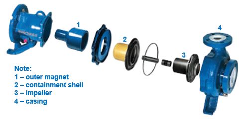
Pump_ptvyfc.jpg


The start up went well however we saw abnormal spike on the electric current of the "A" pump. Shortly after we saw NOx fume and decided to switch to "B" pump & it ran normally up until now. After inspecting the A pump, we found the following pics:
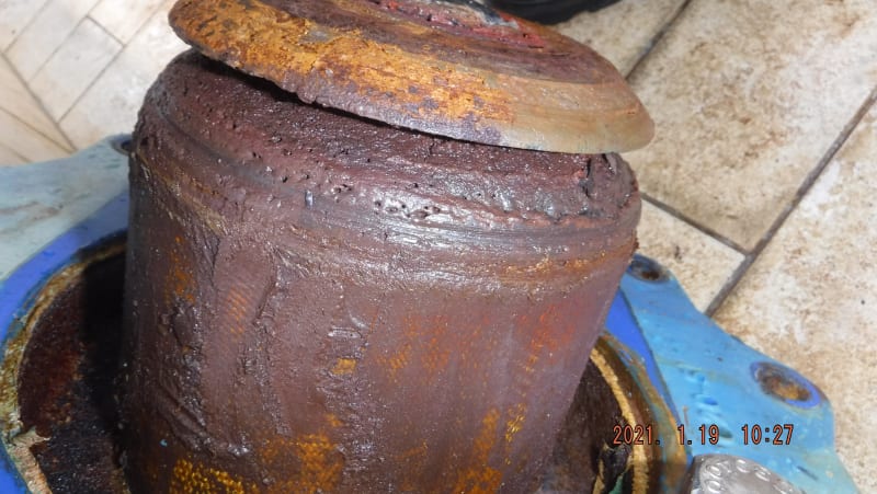
DSCF2618_fjjvmz.jpg

Containment shell worn out due to scratching with magnetic outer drive.
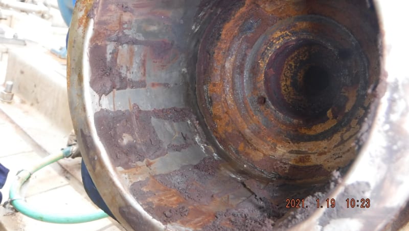
DSCF2617_w8xic9.jpg

Worn out outer magnetic drive

DSCF2607_awon89.jpg

Broken wear ring

This failure mode happens after the pump was changed from C3 to C4 type. Prior changing, the failure mode was different (broken casing and scratching impeller with intact containment shell). After changing, the pump last a year before breakdown, while before changing, the pump only last 1 month before breakdown.
I would really appreciate for any thoughts or comments. Thank you.
Best regards,

Yosep
 
Replies continue below

Recommended for you

I'm still hung up on the photo you shared of the nitric acid that leaked through the containment shell. Any kind of particle accumulation would tend to for a wear ring pattern, no? This leak is in a single point. The fact that the leak is a singular point rather than in a ring shape indicates to me a chemical attack rather than physical phenomenon.

I would recommend you request coupons of this resin from the manufacturer and test it yourselves in your process fluid to see if it is actually resilient. How sure are you of the purity of this nitric acid stream? Any possibility of other contaminants (chlorides?) that may change the potential corrosive nature of this stream?

Lastly, is this containment shell resin fully resistant to HNO3 throughout the entire material? I.e. is the structural winding the same material as the "resistant" internal layer?
 
Going back to the beginning - the fauilures started when the y moved from a C3 type pump to a C4.

The key difference for me is this moving shaft. does it cause mechanical damage?
Does it cause a pressure spike in the fluid coming around the back of the rotor and overstress this casing?
Is there a difference between a C3 and a C4 casing?

how are those containment shells made? they look a bit "manual" with the mesh staying visible.


Remember - More details = better answers
Also: If you get a response it's polite to respond to it.
 
@TiCl4
Hi there. We are absolutely agree with your statement. Yesterday I have sent the containment shell to external lab for failure analysis. Whether the containment shell was damaged because of chemical attack or because of friction with impeller due to thrust balancing. I will update it later in this thread.

@LittleInch
Hi LittleInch. As far as I know, both type of pumps (C3 & C4) has thrust balancing system. The key difference is the size of suction & discharge flanges. C4 has slightly larger size with suction is 3" and discharge is 1.5". While C3 is 2" and 1" respectively. All other parts are the same, including the containment shell.

Best regards,

Yosep
 
The failure lab/forensic analysis will give us the answer ....

While the "nitric acid deposits" are suspicious, I agree with TiCl4 that circular grooves on the containment shell are the hallmark of a magnetized particle failure. The single point leakage without circular grooves makes no sense to me

Were your replacement containment shells purchased from FLOWSERVE or were they repaired shells from some local fiberglass vendor ?

Strainers with magnetic inserts are relatively cheap ....Why are you so reluctant to add one to your system ? ... aside from a modest pressure drop, there is no downside

MJCronin
Sr. Process Engineer
 
Hi MJCronin,

We got the replacement from Flowserve USA via our local distributor. We never repair the broken containment shell. Our current approach is as soon as we find any leaking, however small, we replace the containment shell immediately. - a costly approach but necessary to avoid plant shutdown.

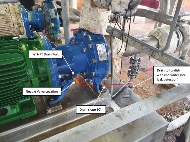
Anyway, our other site in different country also has the same problem with this magnetic drive pump. We use the same spec. They installed a drain to help indicate that a leak started coming, a lagging indicator. But they still do not understand the root cause of the problem.
2022-01-13_08_43_32-Window_heyi0q.jpg


For magnetic strainer, I assume that it was because different failure mode prior changing to the new type, but it is definitely worth a try. I will try to propose a MOC later on about that.

Best regards,
jsasada
 
Hi Jasada,

I encountered a similar failure of magnetic drive but it is with external gear magnetic drive.

Can you check the following

1. NPSH margin during the operation
2. Suction Pressure
3. Vibration
4. shaft Alignment
5. Keyway tolerance

In my encountered of containment can and drive magnet assembly failures is over time when the pump would run continous 24hr x 7 for 1 month.

The magnetic drive assembly shifted its position and shaft touching the containmrnt can wbich create heat to the SS316 containment can. The debris from shaft rubbing of containment can would enter the magnet cavities which damage the magnet overtime and jammed the magnet.

If the pump stop then it would stalled as the debris create friction inside magnet assembly.


Hi BMW,

Would you like to share the pictures please? I am curious with your failure events.

We have confirmed that:
1. NPSHr is below the NPSHa
2. Suction pressure is 350 - 400 kPag
3. Vibration level are normal throughout the time, (0.1 - 2 mm/s)
4. Alignment always performed during pump installation
5. We also always measure the keyway tolerance prior installation.

Best regards,

jsasada
 
Hi Jasada,

Sorey for the late reply.

Please refer to attached


from the pump photo the motor is frame B35, however it was not bolted.

1. How many KW the motor power and RPM .

2. This normally no alignment is done since it is flanged coupled,

3. Another question, how your permanent magnet is sticked into the hub ? Are they using silicon, this worth investigation of the melting temperature of epoxy.

4. Please share the drive magnet photo
 
Are your techs checking clearances before putting the pump in service? Have you sampled the chemical stream for chlorides, heavy metals, etc.?

While I don’t think it’s a contributor does anyone have technical info on Aramid and Carbon fiber reinforced ETFE? From my recollection Aramid isn’t great with nitric
 
Looking at the system into which the pumps are integrated, there could be another origin of the troubles. How do you start up the pumps? If I see it correctly on the P&ID the (continuous) by-pass with the orifice back to the sump ends in the liquid phase. That could cause gas to be trapped during start-up, if also used to prime the pumps.
 
@jsasada

I am currently working on the same exact incident investigation with an Innomag C3-2x1x10 mag drive pump. The process seems to be identical yours. These pumps are our reflux acid pumps for our nitric acid absorber column. 42% nitric acid. Absorber runs around 85-90 psi. We have had multiple failures with this same pump and all have resulted in damage to the containment shell.

Link

We thought at first, that the magnetic drive coupling was either not set properly or the set screws became loose allowing the coupling to move forward tearing apart the containment shell. However, I assembled this pump and found that the coupling would touch off on the pump casing and not touch off on the containment shell.

A key piece of evidence is the pump shaft that is embedded in the containment shell. See linked attachment. Comparing the damaged shell to a brand new shell, I could see that the pump shaft was recessed 0.500 inches deeper into the containment shell. Looking closer I could see that the carbon steel casing that is embedded in the containment shell had been pushed out toward the magnetic coupling. This carbon steel casing houses a composite insert that houses the SiC pump shaft. These components are very rigid.

What we think caused this failure was that the sleeve bearings were starved of lubrication, eventually heating to a point where the sleeve bearings seized on the pump shaft. Considering that the sleeve bearings are housed in the magnetic coupling of the impeller, this would put a lot of torque on the pump shaft and in turn the carbon steel housing in the containment shell. The carbon fiber//ETFE material encases this carbon steel housing. We believe at some point this eventually ripped the ETFE of the containment shell, allowing the pump shaft and carbon steel housing to spin freely. Axial forces eventually pushed this housing and pump shaft toward the magnetic coupling eating away at the composite shroud that houses the pump shaft. Since this pump shaft is bored all the way through, this allowed nitric acid to find a way to the drive end of the pump. See attachment

We have no process data to show that the pump was ran dry, but transient conditions most likely are a factor (shutdowns, startups, etc.) IMO, momentary dry running is unavoidable.


Status
Not open for further replies.

Part and Inventory Search

Sponsor

Back
Top