Eng-Tips is the largest engineering community on the Internet

Intelligent Work Forums for Engineering Professionals

Manifold (distributor) for cooling

Status
Not open for further replies.

drodrig

Mechanical
Mar 28, 2013
260
0
0
DE
Hi there,
ManifoldB_ltmtqw.png


We have to cool down some system at -30C/-22F. We are using ethanol.

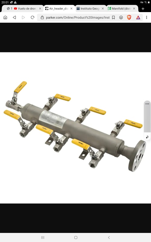
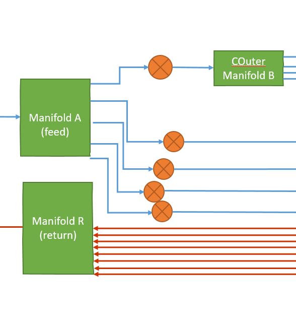
In order to distribute the coolant in the different sections we want to build a manifold using Swagelok connectors.

First I thought about taking an stainless steel pipe, cut it and weld some caps with threaded holes for the connectors. Such:
ManifoldA1_gyjrv0.jpg
ManifoldA2_vxzlb3.jpg


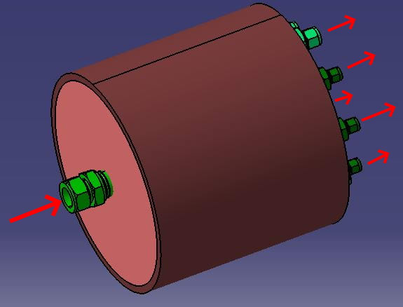
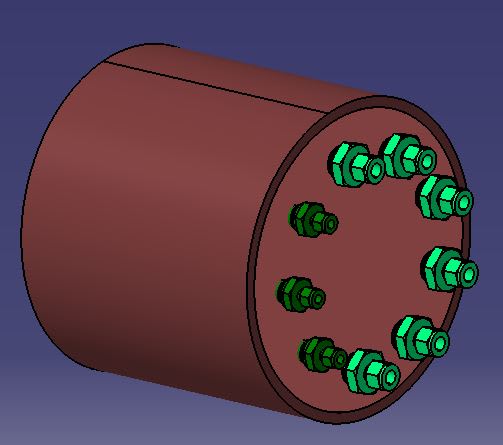
But it would have 275mm/11inches in diameter. Too big and to big mixing volume.

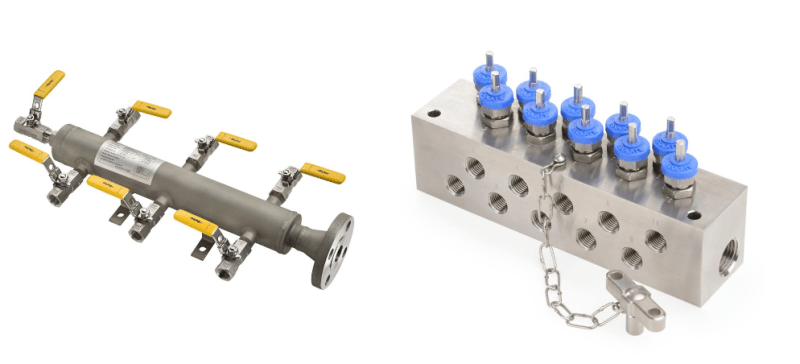
The second idea is taking a square block, drill a big hole almost through (inlet) and then perpendicular holes for the outlets. Such:

ManifoldB_u4btio.png


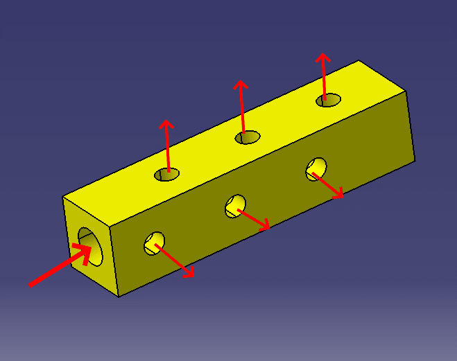
What do you think? How is the most convenient way to build a manifold/distributor?

thanks
regards,
 
Replies continue below

Recommended for you

Depends how you are controlling flow through your branches.

If you're doing it "naturally" then you need a big header for a set of branches.

If you've got individual flow control on each branch then your block looks OK.

I would make the block a bit bigger myself.

Remember - More details = better answers
Also: If you get a response it's polite to respond to it.
 
We plan to have valves in the outlets.

What is a header (I'm not native English speaker)?

How would you make it bigger? in which dimension?

For the cross section (the square) we are limited by the dimension of the biggest Swagelok connector. Although we could drill a bigger bore from the opposite side and then cover it

thanks
 
A header is the bigger pipe which all the branches come off.

Normally there is more flow in the incoming single pipe (the header) so it is bigger and then each branch pipe takes a certain percent of the total flow.

You haven't explained whether the flow is like this ( a big flow splitting down to lots of smaller flows at the same time ) or a smaller flow which is only used by one or two branches at a time. It makes a big difference.

Remember - More details = better answers
Also: If you get a response it's polite to respond to it.
 
What is the least and greatest number of branches that you will flow at once?
If there are not significant flow restrictions in each branch then you should put your valves on the return side of them (not the supply side).
Just remember that a change in the flow in one branch will change them all.
I would suggest making your manifold larger in cross section, and using a larger hole in the center as well as longer so that you can stager the branches further apart. These should help reduce flow interactions.

= = = = = = = = = = = = = = = = = = = =
P.E. Metallurgy, consulting work welcomed
 
Drodig,

I'd recommend just making the "header" larger (say 2x or so the combined cross-sectional area of all your outlet tubing) as well as just making it a normal pipe. Then just weld thread-o-lets along the length of the pipe in the size and orientation that you need for your threaded Swagelok connectors. Welding the Swagelok's outlets along the length of the header avoids the need for making the pipe large diameter to accommodate all of the outlets.

If you do this, you can apply a normal piping code like B31.3 Note that the low temperature will require specific materials and/or tests as called out by B31.3 or other design code that you use. The good thing about using an existing piping code is so you don't have to re-engineer from scratch the header's pressure & temperature limits for a specialty geometry.
 
What is the pressure and flow rates you need?

Headers typically look something like this. Is there a reason you are reinventing the wheel, making swedgelock machine gun things, drilling and taping bars, etc?

Screenshot_20211108-200108_Brave_hccvnd.jpg
 
Back here,

The idea is having 3 manifolds:

- One manifold in the feed with five branches out. Big flow in, distributed out

- One of these branches will go to another manifold, which has 4 branches (going to 4 exact cooling elements)

- 1 manifold in the return collecting all 8 lines back

Manifold_sketch_ax3xoe.jpg


All branches will be working all the time. We are thinking about installing electro-valves; but to be honest we can't check the flow in the branches (apart from theoretical calculations). What is the advantage of having the valves in the return line?

The flow is 20 liters/minute (=317 gallons per hour) and the pressure will be maximum 3 bars (=44 psi)

I see the point of increasing the cross section and separate the outlets. I also see in the Parker website the options, but now I wonder if the block or pipe:
manifold-options_ktiboq.png
 
You do not get the highest possible pressure where you need to use it. For example, valves on the supply side will cause a pressure drop before the fluid is distributed to its device, or point of use. If the receiving device required 40 psi to work, you might lose 10 psi at the valve and your device would only receive 34psig, so it might not work as intended.

 
You may want shut off valves on the supply side, but you don't put control valves there.
as 1503 says they mess with available working pressure.
If you are going to throttle flow it should be done on the return lines.
We always put cheap flow indicators in cooling return lines.
It has saved a lot of equipment.

= = = = = = = = = = = = = = = = = = = =
P.E. Metallurgy, consulting work welcomed
 
If you want all 8 lines to have the same cooling rate you will need to be able to measure flow in each one and have some sort of balancing valve on each line.

Getting equal flow on such a network without automatic flow regulating valves is next to impossible.

As drawn your top 4 lines coming form manifold C will have a lot less flow than the other 4 if they are same size and similar length.

Remember - More details = better answers
Also: If you get a response it's polite to respond to it.
 
As already pointed out above, main problem will be to get equal flow rates (or specific flow rates) in each of the branches. In case you use a pump to achieve the total f!ow, a somewhat higher pressure with a restriction at the end of each branch might help. As this will be tubing, the diameter of the lines will be limited. If you put an orifice or trimming valve at the end of each line, than that restriction will have more pressure loss than the line itself. The resistance of the line itself will have less impact. The system can than also be balanced at start-up or on regular basis.
 
Ok, I understand the situation with the valves in the return

We don't need the exact same flow, but I see the point of the 4 lines top lines (coming out of the COuter Manifold B)

I will increase the pipe diameter between manifolds A and B (with regard to the other 4 -lower- lines coming out of Manifold A) so the flow gets bigger)

thanks. very valuable information

 
Or just tee your incoming line and make the branches the same length to feed manifolds A and B if they all use the same flow in each of the lines.

But getting 8 lines to have anything better than 50% flow difference is not easy. one line will get a lot more and one will get a lot less. Balancing them is difficult.

Remember - More details = better answers
Also: If you get a response it's polite to respond to it.
 
I have to double check the numbers, but in principle the 4 lines coming out of Manifold B need more flow than the single lines out of Manifold A.

Wouldn't be better to have a bigger pipe from A to B to have more flow out of the B lines?

Playing with the valves in the return, wouldn't this help controlling the flow?

cheers,
 
In that case feed manifold B then feed Man A...

Yes but you're playing with eight valves... Every time you change one valve it affects the flow in the other loops.

Remember - More details = better answers
Also: If you get a response it's polite to respond to it.
 
Status
Not open for further replies.
Back
Top