Continue to Site

Eng-Tips is the largest engineering community on the Internet

Intelligent Work Forums for Engineering Professionals

  • Congratulations KootK on being selected by the Eng-Tips community for having the most helpful posts in the forums last week. Way to Go!

Manipulator rotational system problem

Status
Not open for further replies.

ismailtag

Mechanical
Dec 9, 2015
5
Hi everyone.

I am designing a manipulator to hold the dashboard in an automotive company, the manipulator is supposed to carry a load of about 120 Kg at a maximum distance of 5 meters and it is used to transport that payload inside the car.

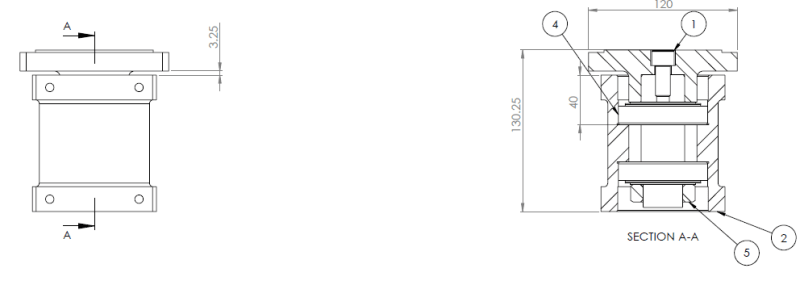
So I designed a system to have several rotational links and one linear motion at the end of the manipulator. As you imagine there is alot of axial load and moment, so I designed the bearing blocks for the rotational links as two taber bearing in an X configurations as seen in this image.
Bearing_block_cc4ch9.png


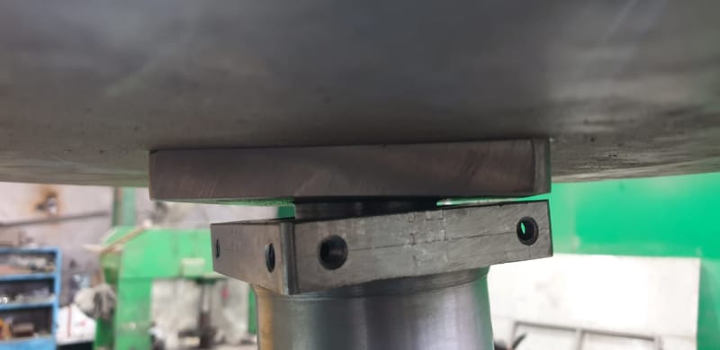
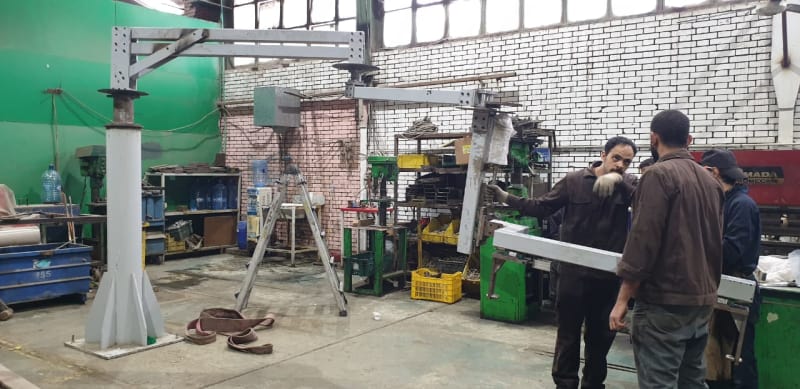
my current problem is that when I add the final link of the system, the manipulator deflects greatly at the bearing blocks as seen in the image.
WhatsApp_Image_2018-12-29_at_15.37.21_hggjac.jpg

Deflection at the bearing block
WhatsApp_Image_2018-12-29_at_15.37.21_1_pk8h1j.jpg


I have tried changing the bearings to larger sizes but its the same problem, I think its a problem of selection of taber bearing. is there any other bearing selection(I have thought about using a combination of thrust bearing and roller bearing) that would solve this problem or is it a problem of needing to use counterweight or wires to support the system while rotating holding the links in place using some pulleys system?

I really need your support in this, appreciate any responses, thanks
 
Replies continue below

Recommended for you

A much smaller and lighter manipulator, mounted on a linear slide (on a set of linear bearings), would seem to be a better solution. Or get the dashboard closer to the vehicle before you have to pick it up, so that the whole apparatus can be smaller.

Work out how much bending moment you are putting on that pivot point with the loads you are applying and the distances that you are using.

The problem that you are trying to solve, has already been solved many times over, because every automotive final assembly plant has a lift-assist mechanism to do exactly this job.
 
I know that it has been solved before, but we dont have the budget to buy the system, we need to do it inhouse, in regards to the linear system, the door of the car must be installed, therefore I need a rotational system to get the dashboard from the rack and into the car while avoiding the door.

I am thinking of reducing the number of links in the system, but i was hoping for a suggestion for a better designed system for the rotational blocks while maintaining its same size or is that not possible just due to the high load?
 
Why not a rigid stub shaft bolted or welded to horizontal member with two ball bearings that can take both radial and thrust load?

Walt
 
You need more distance between the bearings

120 kg @ 5 m = a lot of torque.
 
As I put in my other response, the single bolt to hold the separate pivot seems like a bad idea.
 
Your device will never work acceptably, and I do not see any way to fix what you have. You are trying to reach far beyond what your size of structure can support. It is not even capable of supporting its own weight, let alone a load. Remember that strength and stiffness are two different things. When structural engineers design structures they have to allow for deflection. Floors may be designed to deflect less than 1:180 of the beam length at worst, which would be horrible for your application. You have to get your load to the floor in a much shorter distance, or build a much stouter structure. You can do this by moving your device on floor rails or overhead beams to cover most of the distance you have to cover. Cantilevers are the least stiff design you can use.
 
Found two examples


In both cases, the IP goes in with the doors off the car. In every auto assembly plant that I've been in, the doors are on the body when it goes through paint, then the doors are unbolted and go down sub-assembly lines separate from the main bodyshell, and it's during that time that the IP (and other heavy or big or awkward parts, notably the carpet, the seats, and the headliner) are installed in the main part of the body while the doors are off the car.

In your situation, I can't help that someone failed to plan properly.

It's worth the small bit of labour to unbolt the doors and send them down subassembly lines then reattach them later. It's easier to assemble the main interior parts when the doors aren't in the way, and it's easier to assemble the doors themselves when it's done that way.
 
A standard hub bearing unit for a car wheel will work. Try GM Part No. 1585 1077
(Jimmie Johnson owes me.)
 
At first glance your problem is the prising moment on bolt 1. Work out what angular deflection you'd expect there. The solution is to use a flanged shaft, like the half shaft on a live rear axle.

Cheers

Greg Locock


New here? Try reading these, they might help FAQ731-376
 
An alternative arrangement would be a large diameter axial thrust bearing, a radial ball bearing, and a TRB at the bottom. Same idea as a crane.

Cheers

Greg Locock


New here? Try reading these, they might help FAQ731-376
 
Just a thought... I would get rid of all of the links that you have there, fabricate a deep tapered aluminum section that is affixed to the end vertical of the four-bar linkage that is attached to the crane pedestal and then I would have the final part look something like a coil lifter, kinda like this thing:


But I would have that final C-shape piece able to roll back and forth on the deep tapered aluminum fabrication. As long as you have access above the vehicle, this will allow you to guide the assembly inside.

On the other hand, if you absolutely must use your current setup, use deeper sections on the various links and make them from aluminum and make sure that they are hollow and closed sections to reduce torsional deflection. As for the bearing carrier, you need to spread them out significantly, as some of the other posters have mentioned.

Engineering is not the science behind building. It is the science behind not building.
 
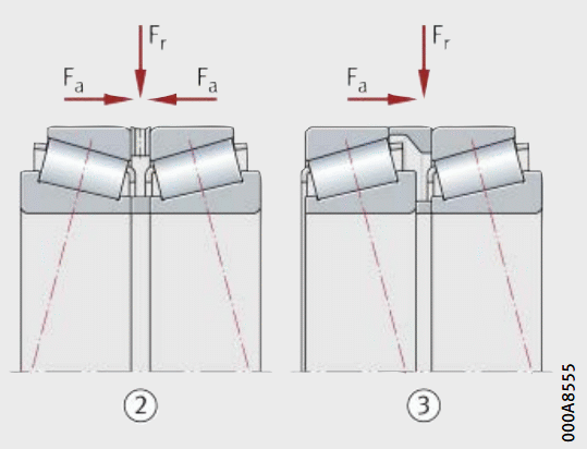
That's an unusual amount of deflection. Is there enough preload on the bearings? Tapered bearings can be installed in two different ways - one maximizes stiffness. I don't recall which way that is.

The shaft and housing are steel, right?
 
The deflection is insane. What angle are the tapered bearings? What tolerances are you using? Do you have the bearings oriented correctly; I think you want either the so-called "O" or tandem arrangement:
bearing_gc9jl0.gif


TTFN (ta ta for now)
I can do absolutely anything. I'm an expert! faq731-376 forum1529 Entire Forum list
 
Hello


That is alot of torque for bearings that are only spaced at about 40mm????. As already mentioned.

125KG x 5000mm))/40=15,625 KG radial load. ?? plus the axial and dead wieght which is not trivial. What are the specs on that bearing that busted?

We use self aligning tapered roller bearings to handle a moment of 681KG at 3M. But they are spaced at 355mm.
 
Ismailtag:
From the look of it, at the moment, that is an awful design, too much deflection and bad joint and arm member design. Show dimensions, member sizes, loads, motion limits, etc. on the existing design. There hasn’t been much real engineering put into the design yet. By the time you get done you may well likely have more time, material, tech. hours and wasted energy invested in a bunch of scrap than if you did go out and buy a properly engineered parts handling system. We need much more info. to really discuss this problem properly. For starters, a floor plan of this immediate handling area. What can you do to shorten handling distances, and amounts of manipulation of the part from pick-up to installation in the car? Is the manipulator in the best position, is the pick-up point optimized and properly oriented w.r.t. the car opening? You have at least four rotary joints and five cantilevered arms/legs (including the center post), can you simplify this with some real improved planning and parts locations, etc. You have to minimize all of the bending moments on members and joints and reduce the torsional loads on the system. Someone else alluded to this, but, could a simplified manipulator move left to right in your photo, on tracks on the conc. floor, so that just one arm rotating and moving up and down could pick-up and position the part, with the straight line movement? There are many ways to skin this cat, but you’ve given no meaningful engineering design info.

 
Status
Not open for further replies.

Part and Inventory Search

Sponsor