Eng-Tips is the largest engineering community on the Internet

Intelligent Work Forums for Engineering Professionals

Massive HSS Beam Torsion and Moment Connection connecting into smaller W-Beam Web (EIT) 13

Status
Not open for further replies.

onlym112

Structural
Sep 9, 2019
45
0
0
CA
Hello,

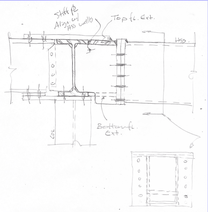
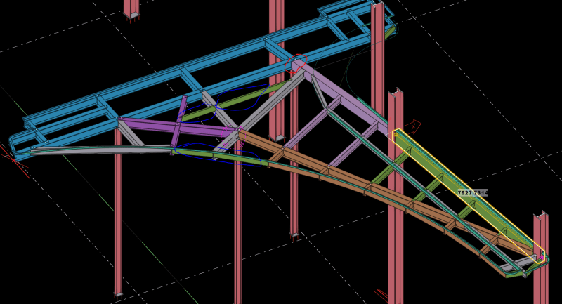
I am currently designing a connection where I have an HSS356x254x13 long side vertical into a W310x45 beam which bear on top of a W200x36 Column. This connection is a moment and torsion connection where the torsion is 50 kNm and moment is 60 kNm. I am having a hard time picturing how I will connect this and was wondering if anyone could give me their insight. I have sketched two possibilities however one of them will not work due to a lack of weld access. Please see the pictures of the model and my sketch below.

Capture_fayznt.png


Capture1_omorqb.png


Capture2_e6nust.png


Capture3_xmq0ho.png


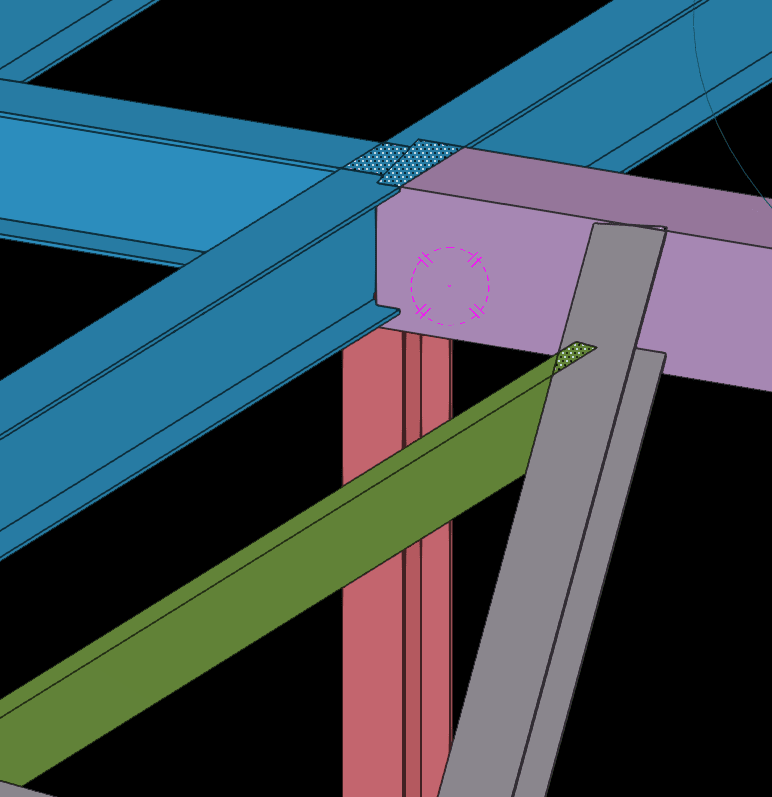
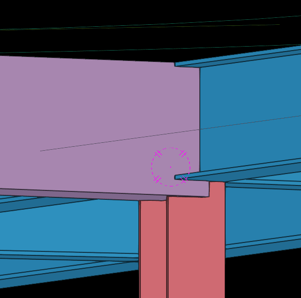
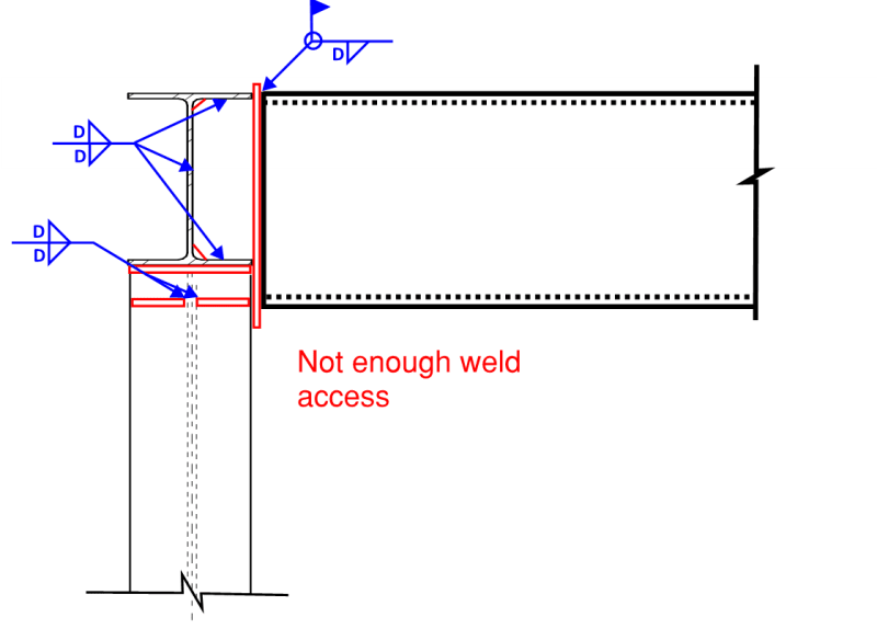
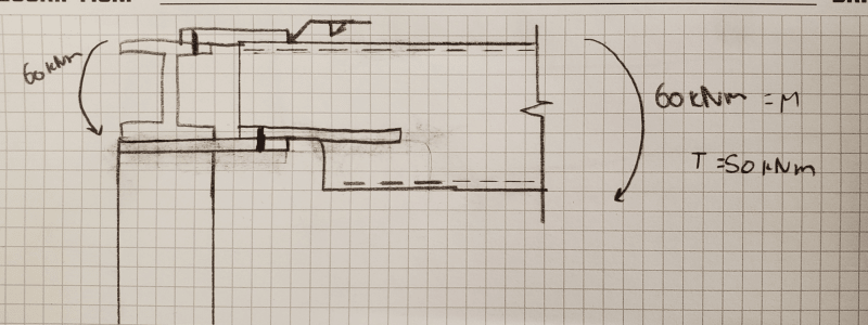
I also considered an endplate option but I am not allowed to portrude my endplate proud at the top to fit my 1" tension bolts. Also there isn't much guidance on a endplate HSS moment connection and based on the HSS size, things can get real ugly and I am not too sure how to handle it. Can anyone give me some feedback? Thank you very much
 
Replies continue below

Recommended for you

I like the big target plate. You're saying that there are weld access problems but I think if you make the plate big enough and get a little clever you should be able to connect it properly.
 
driftLimiter said:
I like the big target plate. You're saying that there are weld access problems but I think if you make the plate big enough and get a little clever you should be able to connect it properly.

Mmm the weld access I was talking about was regarding the stiffeners on the column. To ensure a double sided weld, I need a 30 deg angle to my joint but because I only have 23 degrees..
 
I’ve got some thoughts on this. But a couple questions first. Is this all new construction? The field weld makes me think this might be a retrofit. What is the nature of the load transfer between other members at this location? I’m assuming you’ll need stiffeners over the columns with impacts the discussion of this connection.
 
driftLimiter said:
Can't they just put those stiffeners in there in the shop. Sequentially as they have access?
I have to weld the bearing plate at the end of the column. Whichever I weld first in the shop, there will be one weld that they probably wouldn't be able to get because the access angle is less than 30 deg... Maybe it could work but I don't think so...

CANPRO said:
I’ve got some thoughts on this. But a couple questions first. Is this all new construction? The field weld makes me think this might be a retrofit. What is the nature of the load transfer between other members at this location? I’m assuming you’ll need stiffeners over the columns with impacts the discussion of this connection.

This is all new construction and this canopy the way the architect and the EOR designed it is a nightmare just considering constructability alone as a it is a very complicated frame and everything needs one another to be erected...So this connection I am connecting here according to my design are two frames that will come together on site. This connection has to resist a torsion and a moment that comes from the HSS frame member. The W310x45 supporting beam is one really long beam that runs bears over two column. To the left of member are bunch of moment connection. It is also a cantilever frame. I hope that clear things up..
 
It would be useful to know where the moment and torsion are meant to be transfered to. To the column? To beam behind the connection? To the beam at the connection? All of the above?

I would hope that:

1) The column would receive only axial load.

2) The beam behind the connection would receive moment and no torsion.
 
onlym112, I can't say I follow your description completely, but I get the idea. Complicated/congested joint with load transfer in every direction. Been there and I sympathize. But this is the fun stuff. If connection design was easy, the EOR would do it themselves (tongue-in-cheek comment, take it easy EORs).

In these situations you can clean up some of the congestion by using shop-welded extensions of the members. This provides some separation between your field-connected elements. But use the shop-welded extensions sparingly; you're essentially doubling your connection costs for the extended member when you do this.

See below for a rough sketch on how I'd try to approach this. Shop weld a built-up HSS section to your continuous beam and connect the HSS with a bolted end plate.

Some other general tips on connection design:

[ul]
[li]Try to start with a conceptual sketch of how the node is assembled before you get into too much analysis. Looks like you're already taking this approach[/li]
[li]Further to the point above, try to consider every member in that preliminary sketch. No point of sorting out your HSS problems only to realize that connection material for another member has changed your plans. [/li]
[li]You need to keep in mind what is happening on the other end of the connected member and its general surroundings. This is to ensure the piece can be erected. You can come up with a brilliantly designed connection, but if the beam can't be physically lifted in place then your design is no good.[/li]
[li]You've noted some weld access issues in your preliminary concept. The 30deg rule is good, but it may be worth consulting with shop-staff (if you can). In my experience, depending on what mood they're in I've seen them place some high-quality welds in tight spaces (much less than 30deg access). Additionally, make use of PJP and CJP welds for single sided access where needed (preference is for fillet welds but sometimes you don't have a choice[/li]
[/ul]

e_tips_sketch_woygmu.png
 
I would consider , extending the W200x36 Column to the top and provide through plates (Flange diaphragms ) at the top and bottom level of HSS356 and make the connection apart..

I would provide a sketch but preferred to post the following excerpt ( from HOLLOW SECTIONS IN
STRUCTURAL APPLICATIONS by WARDENIER )


Through_plate_dt7ipt.jpg


..My opinion ..

P.S You may delegate the connection design as long as if you can make sure the connection designer get the full concept of the structure .


Not to know is bad;
not to wish to know is worse.

NIGERIAN PROVERB
 
KootK said:
It would be useful to know where the moment and torsion are meant to be transfered to. To the column? To beam behind the connection? To the beam at the connection? All of the above?
I would like to tranfer the moment to the beam and not put it on my column. If the HSS beam was of the same depth as the w-beam on the other side (moment connection with same magnitude moment) of the main supporting W310x45 beam that bears over two column, I wouldn't have been so concerned but my HSS beam being considerably deeper, I was concerned about how I can transfer this to the beam only in a cost effective yet safe manner.

@CANPRO
Thank you for your guidance and insight.

I have also attached a little model of my canopy roof (building not shown) so you can see the joint that is in consideration (circled in red) along with what this canopy looks like. I Have color coated the members into one matching color for the ones that I will send as one frame in the shop. The four green channels highlighted in blue along with the grey members are stick members.

Capture_mtoxfh.png
 
@JLNJ and @BAretired

Hmmm... sorry... I am not sure what you mean as the EOR provided the canopy design and gave me all the moment and torsion load that I need to design for each node.
 
onlym112 what they're saying is you should politely suggest to the EOR other framing arrangements might be better (but dont say better...say safer, greater factor of safety, yadda yadda - politics and all). Sometimes the primary members should be dropped and concealed in a curved façade to satisfy architectural. Here's a similar example from Structural Steel for Canadian Buildings that does that quite nicely. Throw something like this at them and see what they say. Sometimes we get lucky and it's like the movie inception (...it was the EOR's idea all along).

Capture_tatby5.jpg
 
I don't even understand why the EOR needs to resist torsion with that canopy with the current framing arrangement, and certainly not moment. Seems like poor modelling on their part...
 
The current framing arrangement seems unnecessarily complicated, but there may be a valid reason which we don't know. Like canwesteng, I can't see where the large moment is coming from as the long grey beam with short cantilever is supported near it's end by a column. In any case, the framing should be reviewed by the EOR and try to find a better solution.
 
BAretired said:
but there may be a valid reason which we don't know

Shouldn't this be the default assumption?

The general concept of the framing is similar to the snapshot provided by Enable; the orange and purple members provide the support around the perimeter, curved portion cantilevered from the straight perimeter beams, and the main roof infilled. I can only assume the purple beams have been positioned to support something not shown and it looks like there is a bunch of secondary steel that makes the framing look worse than it is. Regarding the torsion in the HSS - this is just a snapshot of a partially complete model...there could be a 50ft tall sign cantilevering up from this thing for all we know.

I love Eng-Tips. I've learned a lot here and would not be the same engineer I am today if I wasn't an active reader here. However, we (myself included) can come off the rails here sometimes and lose focus on the original question. OP came here with a specific question and provided good info to get the conversation started and it ended up with criticism on the framing plan and advice on how to politely question the EOR on their design.

HTURKAK's suggestion to extend the column up is a good one but doesn't work with OP's current concept of shop-assemblies. Which may not be a bad thing because the assemblies could make the erection of this thing very difficult. To repeat my advice above "You need to keep in mind what is happening on the other end of the connected member and its general surroundings. This is to ensure the piece can be erected. You can come up with a brilliantly designed connection, but if the beam can't be physically lifted in place then your design is no good." - this concern goes up ten-fold when dealing with larger assemblies with multiple connection points.
 
As an engineer who never delegates responsibility for my connections, my comments won’t be valuable. If I can’t do it, I won’t expect someone else to fix my mess.
 
canwesteng said:
I don't even understand why the EOR needs to resist torsion with that canopy with the current framing arrangement, and certainly not moment. Seems like poor modelling on their part...

It does seem like there is a modeling...black box going on here. Is the EOR just fixing everything and reporting what their model spits out? Again, I don't know what I don't know.

It feels like that long, brown girder should be pulling in a lot of the canopy load and leaving those HSS box girders alone in regards to torsion. UNLESS the system is over restrained and the model is revealing that the torsional stiffness of the HSS is greater than the flexural stiffness of the brown girder. Then the HSS may be reaching out and picking up the girder (which wouldn't be wonderful) and resulting in alot of torsion. Am I seeing that right?

Also, what is going on between the cyan girder you're attaching to and the column to the "north east" of it in your figure? Is that cyan girder cantilevering out and just scabbing onto that large column beyond or are they independent of one another? If it's a large cantilever, I feel like it'll be loosey-goosey - especially if you're dumping in torsion. If it's attached to the "north east" column eccentrically and flimsily - I'm not sure what that looks like or how it'll perform.

Again, my head isn't fully into the design and I don't know what I don't know -- but those were two quick first-reaction comments.

"We shape our buildings, thereafter they shape us." -WSC
 
Status
Not open for further replies.
Back
Top