Continue to Site

Eng-Tips is the largest engineering community on the Internet

Intelligent Work Forums for Engineering Professionals

  • Congratulations SDETERS on being selected by the Eng-Tips community for having the most helpful posts in the forums last week. Way to Go!

Maximum depth/Span ratio of Cantilever steel beam 5

Status
Not open for further replies.

ALK2415

Structural
Sep 15, 2014
289
Dear Colleagues
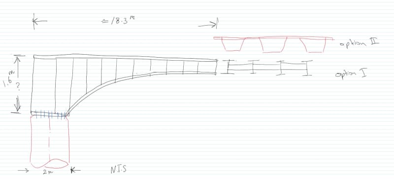
What is the practical depth/Span ratio for a Cantilever beam ?
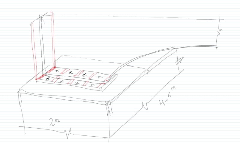
thinking of overhang Plate girders set that cover 60' long [18.3 meters] and 20' wide [6 meters]
thinking of 1/10 ?
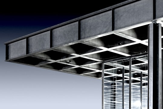
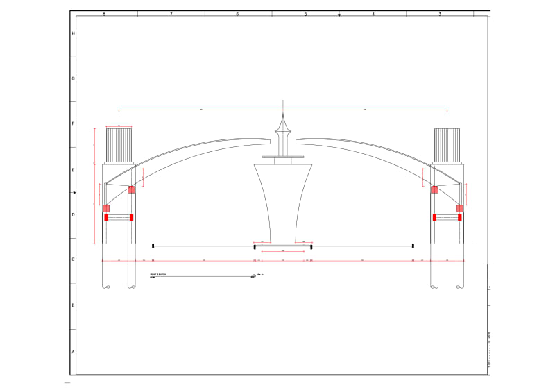
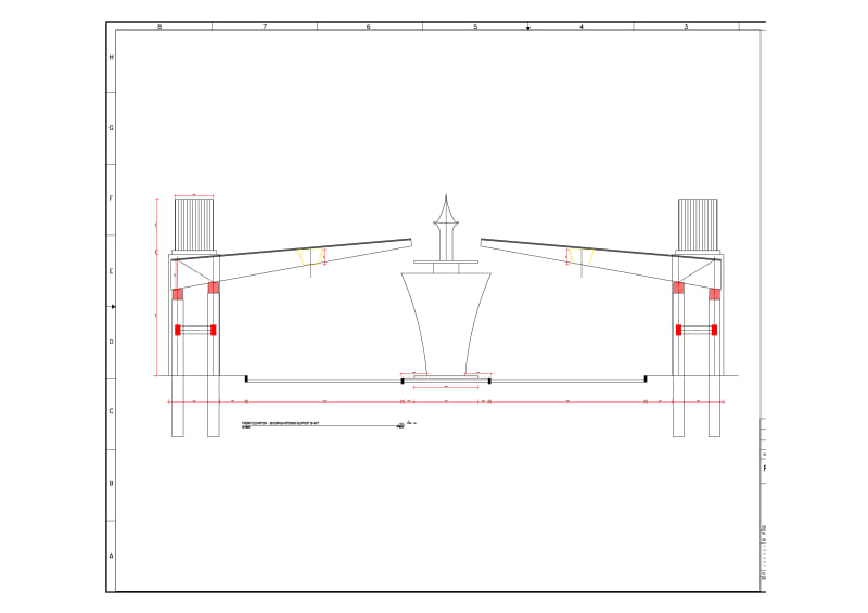
this is kind bizarre, but it a monument kind structure, made for main terminal express welcomed sign

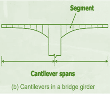
similar to this picture [but unbalanced type]
0x_f8kfou.png
 
Replies continue below

Recommended for you

thinking Also of Box girder
similar to attached picture
Note: your inputs are quite welcome
0x3_aicmmi.jpg


or even grillage system like
0x4_konqfd.jpg
 
For simple spans, we find depth/span ratios in the range of 1/25 to be the most efficient, but cantilever moments will be 4 to 5 times higher than for a simple span of the same length with the same loads (shear is doubled), so the 1/10 may be somewhat shallow; you may want to look more in the 1/8 range. If you have a line-girder analysis program, I suggest trying some different combinations of web sizes and flange sizes to see what works best.

I assume we're only talking about the depth at the support, and it will be haunched. Generally, the labor cost to material cost balance for bridge girders has shifted towards labor being relatively more expensive, so for the most part, it's overall less expensive to use a thicker web and avoid transverse stiffeners. However, assuming a haunched girder, it may be worthwhile to provide a few transverse stiffeners near the support, until the shear drops and the shear buckling strength of the web increases (due to the shallower depth).


Rod Smith, P.E., The artist formerly known as HotRod10
 
Thanks ROD for the guiding
ROD said:
If you have a line-girder analysis program
WILL DO IT USING STAAD.PRO PLATE ELEMENTS
my thinking going toward the variable depth girder [Haunched plate girder - bridge like]
as alternative options:-
1- did add a box-girder shape [relatively hard to manufacture]
2- can same depth [grillage beams system] works ??? [similar to last picture]
Also do you think the seat will be of major design challenge ? [due to turnover vs uplift wind load cases]
X2_iyew2n.jpg


Note: forgave my hand drawing since i did not use it quite often ...
 
the seat of main girder with be above concrete slab [thickness 300]
girders should be total of 4 [and maybe reduced to 3 after analysis results]
shown support configuration :
"this is just preliminarily visualizations"

x1_qgn4h3.jpg
 
Box girders are more common for curved bridge superstructures, because, as you noted, they are more difficult to fabricate, but they have the advantage for lateral stability and resisting the torsional forces imposed on a curved superstructure. You'll likely find them to be a more expensive option for a straight-girder bridge of the size you're designing.

You should only need stiffeners for about the first 3m or so. If you find you need them beyond that, you should consider a thicker web.

Not sure how AASHTO calculates shear capacity for stiffened girders with variable web depths, so that could be fun.

Rod Smith, P.E., The artist formerly known as HotRod10
 
ROD said:
AASHTO calculates shear capacity for stiffened girders with variable web depths
Think it/approximated to different sequenced segments with average depth ?
talking about the design of variable-depth plate girder
Note: the beam actually curved semi-circular not exactly as drawn it
 
Also thinking loudly
adding kind of posttensioning tendons [to reduced deflection]
adding an anchoring to top flange [to counter turnover forces]
is that achievable ?

x3_kfbxk8.jpg
 
Our girder haunches are typically parabolic.

You're planning on cantilevering 60' with no backspan? That's going to be a monumental engineering feat to get the foundation and the girder connection to the foundation to design out. I thought you just weren't showing the backspan. You do realize in addition to the effect of dead load moment (which will be huge), that the tension force on the connection to the foundation due to any live load on the end of the cantilever will be 10 times or more the magnitude of the load, right?

Rod Smith, P.E., The artist formerly known as HotRod10
 
The post seems to come from a student or somebody with extremely limited experience. I find checking previous posts to see the sorts and quality of questions being asked is always a good guide.
 
Adn26 :
I’m inclined to yield to RodS, because he does bridge design every day, and I don’t. While this is not a bridge exactly, it fits his regular/daily experience much better than mine. But, I offer some food for your thought, which I think he will generally agree with, despite my limited bridge design experience. I would put a 10' back span (or some such length backspan) on your main canti. beams and pier/foundation structure, and I would post tension that backspan down to the foundation, much like you might post tension the main canti. beams (main canti. span) to improve stresses and deflections. This will help reduce anchor bolt tension problems at your current beam bearing points, but you will still have a significant cantilever moments/tension loadings, down due to gravity loading of the canti. beams, and upward and/or torsionally due to wind loading, EQ’s, etc. The column/pier/pylon shape might have one edge/face parabolic/curved shaped to kinda match/accentuate the shape of the main canti. beams. You have to pay some attention to torsional and uplift wind loading, etc. on the main beams, the piers and foundations, as well as the unbalanced canti. loadings. You might want to provide an enclosed bot. flange surface (soffit) on the main canti. structure, to improve its structural action both vertically and laterally/torsionally, and to minimize the total lateral structural member area exposed to lateral loading. The backspan, pier/pylon shape might be something kinda aesthetic or monumental in shape, but still helping get that large structural moment down to the foundation. The foundation will be a significant structure too, what with gravity loads, torsional loads and any dynamic loads like wind and EQ’s.
 
dear friends
-its "monument kind structure" two arches meet at middle but without closing the gap
-its Not bridge.
-Not student / Instructor in fact [MSc]
-always humble to ask the experienced engineers like you all
-the design type should challenge your thinking
-my question start with the depth/Span Ration 1/10
- did add some sort of anchoring [back-span] to balance the expected self weight - at the same time the uplift wind forces need to be addressed [ aware of basic mechanics and structural stability]
- thinking also of anchoring [from top flange to bottom support]

x4_kqblwe.jpg


Note: all these drawings are initial/start models will be check/ revaluate using FEM SOFTWARE & and hand calculation [mechanics and structural code of design]
"Challenge should always push ppl to develop new ideas"
 
your INPUTS/GUIDINGS are appreciated and admired
Also a different approach is box girder

x6_kyzig7.jpg


Note: i did my best in isometric drawings - hopefully it will reaches the point
 
You are advising a thesis which consists of designing a cantilever loaded only by dead weight (and some wind, which will be negligible if you use a box section or add stiffeners to give some torsional capacity)? Odd thesis idea, if you ask me.

FYI, the "longest possible cantilever" (loaded only by its own weight), as an academic exercise, is not all that complicated. Use Rayleigh-Ritz method and a beam model, make the shape such that it mimics the bending and shear diagram (linear; could also try parabolic; I don´t remember exactly which one was better, but a google search will reveal it), and solve the internal forces. If you make it a box, torsion will be a non-issue. If you want to minimize the web, add transverse stiffeners to prevent web shear buckling and to improve LTB resistance. The practical limit to span/depth will be lateral-torsional buckling of the cantilever due to self-weight.
 
If this is a thesis the more interesting way about it is to use rhino/grasshopper and their structural modules to let the computer optimize the structure based on set parameters and then do the fine tuning by hand calculations. Really a study on how to set up the appropriate parameters to optimize and see how it affects the output and potential constructability.
 
Because it's not supporting any significant loading beyond its own selfweight, the depth/length ratio could likely be reduced quite a bit from what it would be for a bridge or structure supporting other loads. For you configuration, efficiency-wise the best is likely going to match the height to the width of the base support, since the moment is pretty much the same at the superstructure to foundation interface as it is at the beginning of the cantilever.

It sounds like the shape may be driven more by aesthetics than design efficiency, so you may want to get more clarification on what the limitations are for the foundation width/back span length. If you have enough room for 2 rows of drilled shaft foundations, it will allow you to design the shafts to carry mostly uplift and bearing loads, rather than the shafts needing to be designed for the bending moment. Using 2 rows will also help minimize deflection. If possible, putting the front row of shafts forward, under the arch, will help minimize uplift, since that will put most of the weight of the superstructure on the back row of shafts. Uplift capacity is typically much less than bearing capacity.

Rod Smith, P.E., The artist formerly known as HotRod10
 
@ structSU10
I did some optimization in Ansys, but not with rhino/grasshopper
if you have any reference/paper would be much helpful
Note: we could work as team to produce some meaningful design based on Architectural-geometry vs Structural limitations [AISC LRFD 360-16]
IF YOU HAVE THE TIME ???
now in modeling-checking of applied stress process, then produce the steel drafting
I think some of you did worked this kind of Monument structures or at least know a steel reference that contains similar design cases ..

X1_hwrpld.jpg


the original design post was modified to parabolic one from strait type attched bellow

X2_volmvv.jpg
 
I think you could make it out of steel and use pretensioned anchor rods.

A little rotation at or of the foundation will cause significant deflections of the cantilever tip. This will be difficult to estimate and model.
 
Status
Not open for further replies.

Part and Inventory Search

Sponsor