Continue to Site

Eng-Tips is the largest engineering community on the Internet

Intelligent Work Forums for Engineering Professionals

  • Congratulations SDETERS on being selected by the Eng-Tips community for having the most helpful posts in the forums last week. Way to Go!

Maximum depth/Span ratio of Cantilever steel beam 5

Status
Not open for further replies.

ALK2415

Structural
Sep 15, 2014
289
Dear Colleagues
What is the practical depth/Span ratio for a Cantilever beam ?
thinking of overhang Plate girders set that cover 60' long [18.3 meters] and 20' wide [6 meters]
thinking of 1/10 ?
this is kind bizarre, but it a monument kind structure, made for main terminal express welcomed sign

similar to this picture [but unbalanced type]
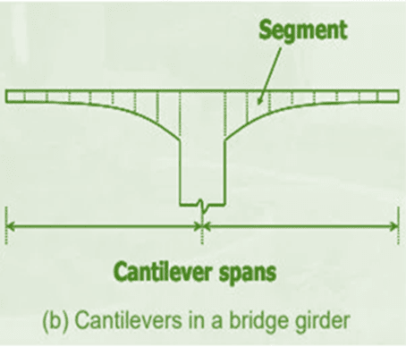
0x_f8kfou.png
 
Replies continue below

Recommended for you

@ JLNJ [all structure is steel] except the cladding will be reinforced masonry brick-wall
JLNJ said:
A little rotation at or of the foundation will cause significant deflections of the cantilever tip
if you noticed what BridgeSmith , did similar foundation
Rod said:
If you have enough room for 2 rows of drilled shaft foundations
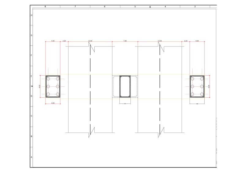
: 6 drilled piers with 80 cm diameter [attached to pile cap and also tie beams {short & long directions}]

trying to resolve the support inclination of main Girders [32 Degree]
X3_j3bvd5.jpg


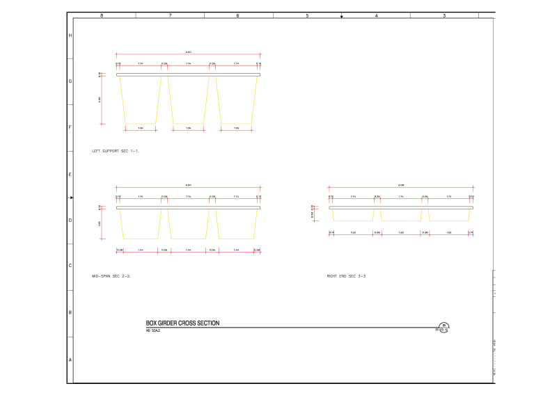
Main Box girders shown in following sections starting from left
X4_fiv3eb.jpg
 
You'll probably need something more substantial (deeper) than what you've shown to connect the front and back columns. You should consider a rectangular or oblong shaft in place of each pair of columns and then connect those directly on top of the 2 drilled shafts below ground. Even then, you may find it difficult to get enough reinforcing into those drilled shafts for the tension, while still maintaining the clearance between bars (5 times the maximum concrete aggregate size).

Rod Smith, P.E., The artist formerly known as HotRod10
 
Dear ROD
still working on the FEM Model
the foundations pile cap is not shown on drawings [nor the Girder internal bracing or wall stiffening]
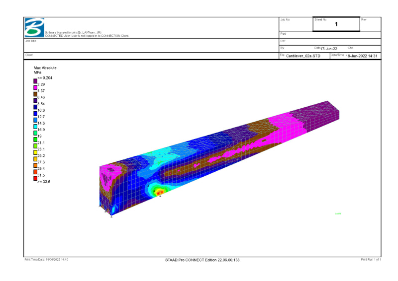
after a while i will present the analysis shown which case of failure [dead-weight or wind] is dominate
the Tie-beams are shown in red [kind of grillage beams that connect all girders to top of each columns longitudinally and transversely]
Any thoughts on the inclined seat (32 degree) ???
Could Anchor cables (in first set of columns) with flat concrete footing be useful here ???
 
I just wanted to be sure you realized that the spacing requirements for the reinforcing in the drilled shafts (transverse and longitudinal) are significantly larger than for a column, due to the limitations on being able to consolidate (vibrate) the concrete (10' is about as deep as they can go).

Inclined seat can be done. Level or stepped would also work. The connection of the end that will provide enough capacity for the tension (uplift) force will definitely take some careful thought.

after a while i will present the analysis shown which case of failure [dead-weight or wind] is dominate

Typically, it would be dead load + wind, assuming you don't have to contend with ice or snow loading.

Rod Smith, P.E., The artist formerly known as HotRod10
 
some updates
Max_Absolute_Stress_01_n3w8by.jpg

and did some modification on geometry
Link
Not final detailing
 
Status
Not open for further replies.

Part and Inventory Search

Sponsor