Eng-Tips is the largest engineering community on the Internet

Intelligent Work Forums for Engineering Professionals

  • Congratulations waross on being selected by the Tek-Tips community for having the most helpful posts in the forums last week. Way to Go!

Maximum possible flatness error ISO versus ASME

Status
Not open for further replies.

Kedu

Mechanical
May 9, 2017
193
0
0
US
Perp_-_Copy_lqlzgw.jpg


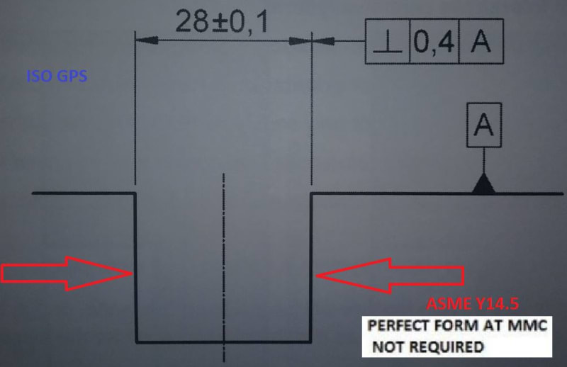
Flatness of the sides shown with red arrows: the combined effect of the two requirements shown (size 28±0.1 and perpendicularity 0.4|A|)

What is the maximum possible flatness error in those 2 cases:

1.) ISO GPS
2.) ASME Y14.5 (with no rule#1 in place)

Is it different or it's the same in both cases and what is the correct value?

I understood that the additional form tolerances can be applied to the shown surfaces (red arrows surfaces) if necessary, but what would be the maximum "as shown" flatness error?
 
Replies continue below

Recommended for you

I am trying to answer those questions, however I am not sure it is a qualified opinion, therefore other members please feel free to disagree with any of my statements.

Maximum possible flatness error per ASME is 0.4
Maximum possible flatness error per ISO is 0.4 + 0.2 = 0.6

Why I would say is different because in ASME the perpendicularity is controlling the UAME (a perfect set of two parallel planes perfectly perpendicular to datum A) and, I think, indirectly controls the flatness of the sides.

In ISO the extracted median plane is the one being controlled, so, unless my understanding is wrong (which is entirely possible either in ISO either in ASME) the size tolerance (0.2) is to be added to the perpendicularity (0.4) in order to get the "built in" flatness.

Any other opinions are very welcomed.


Per ASME Y14.5, It is not entirely clear if the perpendicularity tolerance applies on the right surface or the center plane. It is suspiciously aligned with the size dimension as a center plane control, yet the feature control frame has a leader extended from it as a surface control rather than simply being attached to the extension of the dimension line without the additional arrowhead, or placed beneath the width dimension as a FOS control. In case that the perpendicularity tolerance is a FOS control (applies on the center plane), I don't think that the maximum flatness error of the opposed surfaces is affected. That's because the controlled center plane is derived from the UAME which can have the same solution for different produced features regardless of the actual flatness error of the opposed surfaces.

Per ISO the answer may be different.
 
Burunduk said:
Per ASME Y14.5, It is not entirely clear if the perpendicularity tolerance applies on the right surface or the center plane. It is suspiciously aligned with the size dimension as a center plane control, yet the feature control frame has a leader extended from it as a surface control rather than simply being attached to the extension of the dimension line without the additional arrowhead, or placed beneath the width dimension as a FOS control.

When I determined the numbers above (Maximum possible flatness error per ASME is 0.4; Maximum possible flatness error per ISO is 0.4 + 0.2 = 0.6) I assumed the perpendicularity callout FCF is applied to the center plane (same way as the FCF would have been placed beneath the width dimension).

Burunduk said:
In case that the perpendicularity tolerance is a FOS control (applies on the center plane), I don't think that the maximum flatness error of the opposed surfaces is affected

What do you mean? What does it mean that maximum flatness error of the opposed surfaces is not affected?

What would be your answers for the OP questions?

Thank you
 
greenimi,
I say that the center plane perpendicularity tolerance does not control the form of the opposed surfaces at all. This and the note canceling the requirement of perfect form at MMC lead to an answer that the maximum flatness error is unlimited. The slot could be produced, for example, as two concentric arcs with a radial distance of 28 between them. What drawing requirement prevents this?
 
Burunduk said:
I say that the center plane perpendicularity tolerance does not control the form of the opposed surfaces at all. This and the note canceling the requirement of perfect form at MMC lead to an answer that the maximum flatness error is unlimited. The slot could be produced, for example, as two concentric arcs with a radial distance of 28 between them. What drawing requirement prevents this?

Are you taking about the ISO, about the ASME or about both?

 
Hi All,

Per ISO 1101, it is clear that the perpendicularity tolerance does not apply to just one side of the slot. It applies to the median plane of the slot, which would limit the flatness error of the median plane to a maximum of 0.4. How much does this limit the flatness error of each side of the slot? It's probably 0.4 but I haven't thought it through.

Per ASME Y14.5, it is less clear what the perpendicularity tolerance applies to - there are no examples where the drafting is quite like that. But having the leader in line with the dimension line is a strong indicator, so let's say that it doesn't apply to just one side of the slot. So it would apply to the centerplane, which is by definition perfectly flat. How much does this limit the flatness error of each side of the slot? Not at all.

Evan Janeshewski

Axymetrix Quality Engineering Inc.
 
axym said:
It applies to the median plane of the slot, which would limit the flatness error of the median plane to a maximum of 0.4. How much does this limit the flatness error of each side of the slot? It's probably 0.4 but I haven't thought it through.

If the ISO median plane is anything like the ASME median plane, I would say that theoretically, side faces with large form error can produce a perfectly perpendicular and flat median plane, as long as the actual shape of the slot comes out perfectly symmetrical regardless of the flatness error of each of the sides. Is this incorrect?
 
Evan,

Looks like I was wrong on my "calculation" on the ASME version. I said: Maximum possible flatness error per ASME is 0.4
You said: infinity (flatness error is not controlled at all)

You have 1-0


Evan said:
Per ISO 1101, it is clear that the perpendicularity tolerance does not apply to just one side of the slot. It applies to the median plane of the slot, which would limit the flatness error of the median plane to a maximum of 0.4. How much does this limit the flatness error of each side of the slot? It's probably 0.4 but I haven't thought it through

Could you explain a little bit why 0.4 is, in your opinion, the maximum flatness ?
I said in my earlier post: Maximum possible flatness error per ISO is 0.4 + 0.2 = 0.6

You have the right to change your mind.

Am I wrong again?


Burunduk,

I believe that the ISO median surface is similar to the ASME median plane. I would agree that slot faces with large, but symmetrical, form error can produce a perfectly flat and perpendicular median plane. I would also agree that slot faces with large, but non-symmetrical (arc-shaped) form error can produce comparable form error in the median plane.

greenimi,

I'm thinking of a slot whose median plane has a flatness error of 0.4, and trying to envision what kind of form error on the two side faces would cause that. I initially only thought of cases where the two sides are arc-shaped or wavy, and "in phase" so that the peaks and troughs on one side line up with those on the other side. Bending the median plane by 0.4 causes each of the two sides to bend by 0.4 as well. I hadn't thought of any cases where the flatness of one of the sides is worse than 0.4, that doesn't make the flatness of the median plane worse than 0.4 (the local size must also stay within 28 +/- 0.1). But I was only looking at cases in which the local width of the slot was constant.

I wasn't sure where you got 0.4 + 0.2 = 0.6, but now I think I see what you're getting at. The local width doesn't need to be constant. If the slot is narrow (27.9) at the top and bottom and wide (28.1) in the middle, then one side could have flatness error larger than 0.4 and still maintain a median plane flatness of 0.4. I get a worst-case flatness of 0.55 on one side, not 0.6. Maybe we were both wrong ;^).

Evan Janeshewski

Axymetrix Quality Engineering Inc.
 
axym said:
I believe that the ISO median surface is similar to the ASME median plane. I would agree that slot faces with large, but symmetrical, form error can produce a perfectly flat and perpendicular median plane.

Then would it be wrong to say that the perpendicularity tolerance does not affect the flatness of the slot surfaces, neither per ASME nor per ISO? It seems to me that if the median plane error indicates the surface error of the opposed surfaces only sometimes with some specific condition (specific shape) and tells nothing about the error in another case, then we can't really make a calculation based on it (the 0.4 value).
 
Burunduk,

I would say that the perpendicularity tolerance affects the flatness of the slot surfaces per ISO. But I suppose that we need to specify exactly what is meant by "affects the flatness".

There is a limit to the worst-case flatness error (0.55 by my calculation), and the perpendicularity tolerance contributes to that limit (along with the size tolerance). In other words, the perpendicularity tolerance on the median plane affects the worst-case flatness error of the sides. But as you say, there is not a correlation between the actual perpendicularity error of the median plane and the actual flatness error of the sides. So I agree that the perpendicularity error of the median plane is not a good indicator of the flatness error of the sides.

Evan Janeshewski

Axymetrix Quality Engineering Inc.
 
Evan,

Could you, please, let me know how you came up with o.55 value (worst case flatness error)?
(I guess greenimi's wrong value is just a simple addition between perpendicularity 0.4 and total size variation 0.2). Thank you much
 
Kedu,

I got the 0.55 value by drawing the part geometry described in the April 7 21:36 post. It turns out that I made a mistake in the drawing, and the maximum flatness error of one side is actually 0.5. and not 0.55.

I tried to upload a picture but for some reason it's not working. Imagine a feature that is 27.9 wide at both ends, and 28.1 wide in the middle. Then bend it so that the median plane is an arc that is bent by 0.4 (flatness of 0.4). One side should have a flatness of 0.3 and the other side has a flatness of 0.5.

Evan Janeshewski

Axymetrix Quality Engineering Inc.
 
axym said:
Per ASME Y14.5, it is less clear what the perpendicularity tolerance applies to - there are no examples where the drafting is quite like that.

Evan,

I've seen fig 4-43/ 2009 where drafting is similar with the OP's example. The standard figure shows angularity, but, as you sure know, angularity can replace perpendicularity and parallelism.
Don't you think it's a valid callout?

Different subject:

Speaking about fig 4-43 / 2009 I've seen a good discussion on linkedin Applied Geometrics forum about the Unless Otherwise Specified UOS note.
Maybe you (Evan) can shoot some light into that controversy too...


greenimi,

The callout in the OP's example is quite similar to Fig. 4-43, but it's not exactly the same (there is an extra arrowhead). I would say that it's close enough and that it's clear that the perpendicularity tolerance applies to the centerplane. The OP's example is ISO GPS so the drafting is not going to be identical to ASME.

Evan Janeshewski

Axymetrix Quality Engineering Inc.
 
Evan and all,

axym said:
The callout in the OP's example is quite similar to Fig. 4-43, but it's not exactly the same (there is an extra arrowhead).

May I ask: if in the OP's case the arrows for 28±0.1 dimension are reversed (I mean instead of pointing as currently shown rotate both of them with 180 degrees and move them outside the slot), then would be no extra arrowhead because the most right arrows will overlap, then why the OP's scheme is not the same as fig. 4-43.

I am confused about the difference between ISO's drafting style and ASME's one. If the OP's example is ISO GPS then why is not identical with ASME (if the arrows are reversed) ?

Could anyone shoot some light into this issue?

 
Status
Not open for further replies.
Back
Top