Continue to Site

Eng-Tips is the largest engineering community on the Internet

Intelligent Work Forums for Engineering Professionals

  • Congratulations IDS on being selected by the Eng-Tips community for having the most helpful posts in the forums last week. Way to Go!

Maximum possible contact and a single solution

greenimi

Mechanical
Nov 30, 2011
2,385
Per ASME Y14.5-2018
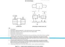
7.12.4 Pattern of Features of Size RMB
When RMB is applicable in a feature control frame to common datum features of size used to establish a single datum, the true geometric counterpart of each feature shall be fixed in location relative to one another. The true geometric counterparts shall expand or contract simultaneously from their worst-case material boundary to their LMB until the true geometric counterparts make maximum possible contact with the extremities of the datum feature(s). When irregularities on the feature(s) may allow the part to be unstable, a single solution shall be defined to constrain the part.
Questions:
1.) What means maximum possible contact?
2.) What means "single solution" default for unstable/rocking datum features (that replaces the former default of a candidate datum set) ?
 
Replies continue below

Recommended for you

Another ad hoc answer to a gap in the standard.

The section and the figure are created for the single case of two nominally coaxial features and fail for any other case of such references. It's a single case and a likely ad hoc solution that doesn't apply to most any other RFS "pattern."

Clearly, if the features are of nearly perfect form and identical size there is no problem. I think that is obvious enough to not be worth using as a basis for a conclusion of any kind.

" It is all matter of technique, which is always imperfect and the Y14.5 standard is not expected to cover."

Gaps in Y14.5 cannot be excused for technique being imperfect. The standard is intended to communicate the limits of imperfect part variation and perfecting the basis of measurement, not ignoring imperfections in measurement.
I mean that I don't mean any malice.
And that's the problem. To quantify your post here. ASME does its best to explain every circumstance. It's literally impossible to
Try to cover ever billion circumstances.
But to say it's the best we have. And it is what it is it is humanly impossible to make it perfect.
I think we can acknowledge that and deal with it.
No mater how hard it can be.
I think the best way to learn from it is to break it down section by section
Then define its meaning.
My thoughts to much wording to me , becomes to confusing. And probably represent most guys on floor. Because that's where I started from.

I am a big believer in presentations , graphical in nature. It just makes more sense. I remember when an other posted geotolerancing hand book
It was a very concise in explaining GD&T.
Don't remember the exact name so correct me if incorrect.
 
The standard does have gaps but this one is not exactly one of them. The only problem here is some unnecessary and partial details (true geometric counterparts contracting or expanding simultaneously, in 7.12.4) that should not have been mentioned. Once they were they are a cause of confusion and distraction. The way to avoid falling into that trap is to know how to separate the wheat from the chaff. The intent is simultaneous constraints with equal ability for the pattern members to effect, and that intent does get communicated.
 
The standard does have gaps but this one is not exactly one of them. The only problem here is some unnecessary and partial details (true geometric counterparts contracting or expanding simultaneously, in 7.12.4) that should not have been mentioned. Once they were they are a cause of confusion and distraction. The way to avoid falling into that trap is to know how to separate the wheat from the chaff. The intent is simultaneous constraints with equal ability for the pattern members to effect, and that intent does get communicated.
Yes very well said, continuous improvement is real. Thank you for your contribution.
 
The standard does have gaps but this one is not exactly one of them. The only problem here is some unnecessary and partial details (true geometric counterparts contracting or expanding simultaneously, in 7.12.4) that should not have been mentioned. Once they were they are a cause of confusion and distraction. The way to avoid falling into that trap is to know how to separate the wheat from the chaff. The intent is simultaneous constraints with equal ability for the pattern members to effect, and that intent does get communicated.

So, if "The true geometric counterparts shall expand or contract simultaneously" should NOT have mentioned in 7.12.4, then how the end user would have understood the DEFAULT condition as being "simulaneously" (simultaneity) and not being the "maximum possible contact" ?

Other figures RMB within 2018 make reference to "make maximum contact" (7-34) hence I think consistency should play a key role in those figures.
Therefore, should I understand that the "maximum contact" is the main driver for a single feature at RMB, but when a pattern of features is used RMB then the main driver become "simultaneity" (and the maximum contact becomes a secondary concern)?

By the way, I've never thought about "different rate" to achieve this "simultaneous" condition......you might be right. I am still trying to get my arms around the physical realities of such concept.
 

Part and Inventory Search

Sponsor