Continue to Site

Eng-Tips is the largest engineering community on the Internet

Intelligent Work Forums for Engineering Professionals

  • Congratulations cowski on being selected by the Eng-Tips community for having the most helpful posts in the forums last week. Way to Go!

Maximum possible contact and a single solution

greenimi

Mechanical
Nov 30, 2011
2,391
Per ASME Y14.5-2018
7.12.4 Pattern of Features of Size RMB
When RMB is applicable in a feature control frame to common datum features of size used to establish a single datum, the true geometric counterpart of each feature shall be fixed in location relative to one another. The true geometric counterparts shall expand or contract simultaneously from their worst-case material boundary to their LMB until the true geometric counterparts make maximum possible contact with the extremities of the datum feature(s). When irregularities on the feature(s) may allow the part to be unstable, a single solution shall be defined to constrain the part.
Questions:
1.) What means maximum possible contact?
2.) What means "single solution" default for unstable/rocking datum features (that replaces the former default of a candidate datum set) ?
 
Replies continue below

Recommended for you

Another ad hoc answer to a gap in the standard.

The section and the figure are created for the single case of two nominally coaxial features and fail for any other case of such references. It's a single case and a likely ad hoc solution that doesn't apply to most any other RFS "pattern."

Clearly, if the features are of nearly perfect form and identical size there is no problem. I think that is obvious enough to not be worth using as a basis for a conclusion of any kind.

" It is all matter of technique, which is always imperfect and the Y14.5 standard is not expected to cover."

Gaps in Y14.5 cannot be excused for technique being imperfect. The standard is intended to communicate the limits of imperfect part variation and perfecting the basis of measurement, not ignoring imperfections in measurement.
I mean that I don't mean any malice.
And that's the problem. To quantify your post here. ASME does its best to explain every circumstance. It's literally impossible to
Try to cover ever billion circumstances.
But to say it's the best we have. And it is what it is it is humanly impossible to make it perfect.
I think we can acknowledge that and deal with it.
No mater how hard it can be.
I think the best way to learn from it is to break it down section by section
Then define its meaning.
My thoughts to much wording to me , becomes to confusing. And probably represent most guys on floor. Because that's where I started from.

I am a big believer in presentations , graphical in nature. It just makes more sense. I remember when an other posted geotolerancing hand book
It was a very concise in explaining GD&T.
Don't remember the exact name so correct me if incorrect.
 
The standard does have gaps but this one is not exactly one of them. The only problem here is some unnecessary and partial details (true geometric counterparts contracting or expanding simultaneously, in 7.12.4) that should not have been mentioned. Once they were they are a cause of confusion and distraction. The way to avoid falling into that trap is to know how to separate the wheat from the chaff. The intent is simultaneous constraints with equal ability for the pattern members to effect, and that intent does get communicated.
 
The standard does have gaps but this one is not exactly one of them. The only problem here is some unnecessary and partial details (true geometric counterparts contracting or expanding simultaneously, in 7.12.4) that should not have been mentioned. Once they were they are a cause of confusion and distraction. The way to avoid falling into that trap is to know how to separate the wheat from the chaff. The intent is simultaneous constraints with equal ability for the pattern members to effect, and that intent does get communicated.
Yes very well said, continuous improvement is real. Thank you for your contribution.
 
The standard does have gaps but this one is not exactly one of them. The only problem here is some unnecessary and partial details (true geometric counterparts contracting or expanding simultaneously, in 7.12.4) that should not have been mentioned. Once they were they are a cause of confusion and distraction. The way to avoid falling into that trap is to know how to separate the wheat from the chaff. The intent is simultaneous constraints with equal ability for the pattern members to effect, and that intent does get communicated.

So, if "The true geometric counterparts shall expand or contract simultaneously" should NOT have mentioned in 7.12.4, then how the end user would have understood the DEFAULT condition as being "simulaneously" (simultaneity) and not being the "maximum possible contact" ?

Other figures RMB within 2018 make reference to "make maximum contact" (7-34) hence I think consistency should play a key role in those figures.
Therefore, should I understand that the "maximum contact" is the main driver for a single feature at RMB, but when a pattern of features is used RMB then the main driver become "simultaneity" (and the maximum contact becomes a secondary concern)?

By the way, I've never thought about "different rate" to achieve this "simultaneous" condition......you might be right. I am still trying to get my arms around the physical realities of such concept.
 
greenimi,
My opinion is that both the simultaneity of application of constraints and the "maximum possible contact" are required characteristics of a pattern of features of size (or "common datum features" of size) at RMB. These two things should not be in conflict (no reason for them to be). "Maximum possible" contact is related to the fact that the true geometric counterparts are basically constrained to each other, so they can't make the fullest contact with the actual features like an Unrelated AME does, but they must make the "maximum possible" (contact, under these conditions). I think there are already several guidelines offered in this thread for practically workable "between the lines" interpretations of the Y14.5 wording.
 
Last edited:
The standard does have gaps but this one is not exactly one of them. The only problem here is some unnecessary and partial details (true geometric counterparts contracting or expanding simultaneously, in 7.12.4) that should not have been mentioned. Once they were they are a cause of confusion and distraction. The way to avoid falling into that trap is to know how to separate the wheat from the chaff. The intent is simultaneous constraints with equal ability for the pattern members to effect, and that intent does get communicated.
I believe what the issue is , the cart before the horse. Unless an Engineer under stands the concept of different types of assemblies and what the intent is it will be more interpretable.
As the video I posted earlier the management of tolerancing. What goals are, and what the intent.
For example a bearing on an axel. Where is the press fit, and where is the slip fit. And what type of bearing.

What type of fit between with a bolted assembly.
What is precision fir required on shaft rotating 10k rpm. What is the out of balance required.
and how do I apply GD&T.
 
GD&T is only part of the game plan on drawing.
What is material required.
What heat treat required and what hardness.
What is the application .
What is the precision
Which GD&T is more applicable .
GD&T is only required to inspect and record for Quality Assurance, and the part is to the drawing. But as said earlier, the Engineer must be experience to apply it correctly.
 
I am changing hats , So as a precision mechanical inspector. The Engineer or Engineers have applied requirements. Gd&T.
The tolerancing applied is not for debate.
My position is to know what means and how to measure it. I have philosophy can I setup and measure at least to methods. Of the results are
Marginal. I will measure it differently. To verify my results. CMM or on the surface plate. I can do both. My job is to make sure it is in compliance.
If it passes is great . If not write up an discrepancy report and for forward it to engineering. And wait for the Engineer to disposition.
 
In my young days I had the privilege to be in an apprenticeship. That allowed me to work and learn different departments. Shop, inspection, engineering, tool design, old style drafting board.
Met lab, NDT level 2,
My point is not to boast but to state that every person get a good under standing of all these areas. As well as get the education which is so important. It will all fall in place. apprenticeship will very much help in one's career. It has done me well.

I agree with you. With only one caveat: We have to understand what the theory -read "the standard"- requires (and what does not require) - before we can apply such of said theory in any sort of practical way. We are debating/ clarifying here mostly our individual understandings of the theory. Burunduk, looks like, has a very good grasp on the theory so we are finding a common denominator ............
 
Last edited:
I agree with you. With only one caveat: We have to understand what the theory -read "the standard"- requires (and what does not require) - before we can apply such of said theory in any sort of practical way. We are debating/ clarifying here mostly our individual understandings of the theory. Burunduk, looks like, has a very good grasp on the thoery so we are finding a common denominator ............
Greenimi
That's good, but don't take offense I do the same.
Maybe trying to hard. take time to think about what he said. Read it several times if necessary
Then write down questions.
 
I use to have habit of written notes because I would review my old notes how I would resolve an issues, old job old problems that was not common.
 
In my young days I had the privilege to be in an apprenticeship. That allowed me to work and learn different departments. Shop, inspection, engineering, tool design, old style drafting board.
Met lab, NDT level 2,
My point is not to boast but to state that every person get a good under standing of all these areas. As well as get the education which is so important. It will all fall in place. apprenticeship will very much help in one's career. It has done me well.

Appreciate you sharing that. You don’t see a lot of young engineers these days who are that into the craft and actually take the time to keep learning. Sounds like you were one of the rare ones, and still are. Did you have any favorite books or handbooks back then? I get the feeling those used to be gold. Now it’s just, “Why read when you can ask Google or chat with a robot?” Patience and deep learning? Out the window. Everyone just wants instant answers with zero effort.
 
Appreciate you sharing that. You don’t see a lot of young engineers these days who are that into the craft and actually take the time to keep learning. Sounds like you were one of the rare ones, and still are. Did you have any favorite books or handbooks back then? I get the feeling those used to be gold. Now it’s just, “Why read when you can ask Google or chat with a robot?” Patience and deep learning? Out the window. Everyone just wants instant answers with zero effort.
Hey my favorite books were old I unfortunately , I moved so I gave many of them away.
Dudley's gear design
Earl buckingham this was one of My fav
Series of different subjects
Fellows shaper, gear design
Barbercoleman hob design
Don't remember the author die design
I enjoyed physics, chemistry, engineering,
Mathematics. Drafting ,
And much more
That inspires. Thank you.
 
greenimi,
My opinion is that both the simultaneity of application of constraints and the "maximum possible contact" are required characteristics of a pattern of features of size (or "common datum features" of size) at RMB. These two things should not be in conflict (no reason for them to be). "Maximum possible" contact is related to the fact that the true geometric counterparts are basically constrained to each other, so they can't make the fullest contact with the actual features like an Unrelated AME does, but they must make the "maximum possible" (contact, under these conditions). I think there are already several guidelines offered in this thread for practically workable "between the lines" interpretations of the Y14.5 wording.

Do you kow how ISO GPS is treating this pattern RMB issue?

I would even ask pmarc for the rescue ---if you are reading this discussion 🙏

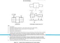
I found this on ISO5459 and states ..." with objective function "MINMAX" to minimize, simultaneously and globally, the maximum distance between......"
Is what you described above (about "different rates" -- which is new and interesting concept for me) in alignment with ISO GPS description or you imagined something totally different?


ISO5459 - Copy.jpg
 
Do you kow how ISO GPS is treating this pattern RMB issue?

I would even ask pmarc for the rescue ---if you are reading this discussion 🙏

I found this on ISO5459 and states ..." with objective function "MINMAX" to minimize, simultaneously and globally, the maximum distance between......"
Is what you described above (about "different rates" -- which is new and interesting concept for me) in alignment with ISO GPS description or you imagined something totally different?


View attachment 8031
I would recommend a new post
 
greenimi,
This ISO figure more or less corresponds with my interpretation as I wrote in post #16 in this thread:
"My own way to tackle this would be to simply say that the common axis should be established by two Related AMEs, which are "Related" not because of any preceding datums in the datum reference frame, but because, although forming a primary true geometric counterpart, they must be perfectly coaxial to each other."

As for TGCs/simulators contracting at different rates, my opnion is that it should not be mandatory. But I think that, perhaps unfortunately, it is the only way to achieve the goal if the requirement from para 7.12.4 is to be followed. Specifically the need to start contracting at the same time from the Outer Boundary:

"The true geometric counterparts shall expand or contract simultaneously from their worst-case material boundary to their LMB until the true geometric counterparts make maximum possible contact with the extremities of the datum feature(s)".
 
Per the 2019 Math standard

""""""This revision includes a new stabilization definition for irregularities on datum features specified at RMB, which provides an alternative to the candidate datum set. SC5 had moved toward the concept of a single-stable solution that minimizes the separation between the datum feature and the true geometric counterpart, and SC5.1 was asked to study the concept and recommend a mathematical definition. A stable Constrained L2 datum definition was selected, which applies as an alternate stabilization definition for Y14.5-2009 and the default stabilization definition for Y14.5-2018. See Nonmandatory Appendix B for results of the study and mathematical definitions.
The constrained least squares simulator (constrained L2) behaves remarkably well. In cases where there are clear points of contact that a metrology engineer would choose, the constrained least squares simulator chooses them. In cases where the part “rocks,” the constrained least squares simulator chooses an equalized solution that a metrology engineer might have chosen. In summary of the detailed comparison below, the constrained least squares simulator has excellent externality and contact. It has good plausibility, and good repeatability across parts."""""""""


However ADAPTING those requirements to the common datum at RMB (Pattern of Features of Size RMB) is a little too much for me to comprehend.
 
"the constrained least squares simulator" is only available to users of CMMs, the main reason for the existence of many explanations. It also does not offer any particular connection to the actual installed condition of the features or the entire part because assemblers do not use least squares when installing parts.

"expand or contract simultaneously from their worst-case material boundary" is also a CMM-only function and, strangely, is something that isn't actually done. The mathematics is they start either from 0 or from infinity or, more likely, just do a least squares approximation directly from the captured data with no expansion or contraction whatsoever.

Even in a gauge situation, there would be no need for a collet, for example, to be set with infinite precision, to the worst-case material boundary before inserting the part that will use that as the True Geometric Counterpart/Datum Feature Simulator.

What is done is not what the standard says is done. What would make their statements true is adding "As if" the following were happening. It's as if they expand or contract simultaneously, but they actually do not.

In practice there is some amount of deformation of the datum feature surfaces to provide enough grip to keep the part stationary against external forces, even if they are limited to gravity loads.
 

Part and Inventory Search

Sponsor