Eng-Tips is the largest engineering community on the Internet

Intelligent Work Forums for Engineering Professionals

  • Congratulations waross on being selected by the Tek-Tips community for having the most helpful posts in the forums last week. Way to Go!

Maximum socket weld size 1

Status
Not open for further replies.

omegasamurai

Mechanical
Jul 17, 2019
6
0
0
US
Hey guys,
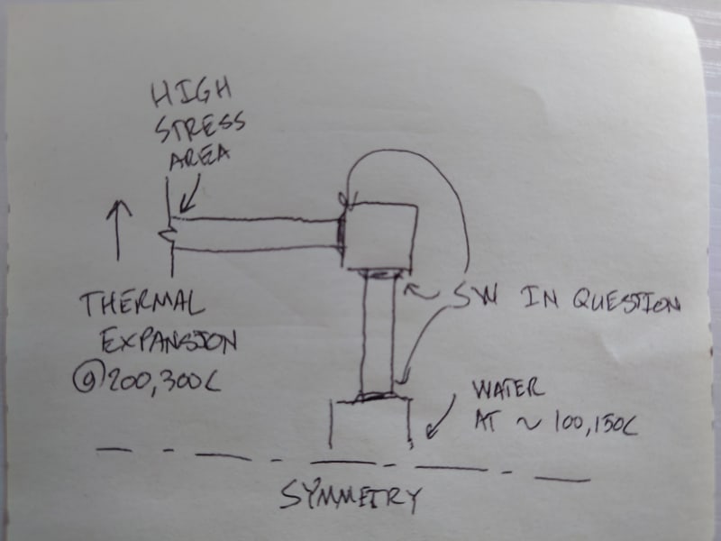
I'm working on some 1.5" piping that's going to be in Hi-temperature steam service. I was having a little argument with my boss because due to him wanting to use a higher weld size (1.5 x Tm) than required by ASME B31.1, because we've had pipe break in the field in this application before. His opinion is generally that "more is better."

My understanding is that this is definitely not true for socket welds/fillet welds, but I'm having trouble finding a reference or resource that definitively ties fillet weld size to the greater stress concentration/likelihood of weld defects, etc.

Does anyone have a good reference for socket weld/fillet welds stress factors? Also what are people's practical experiences with overly large socket welds? (if you have any)

Appreciate the help.​
 
Replies continue below

Recommended for you

And the reason you can't butt weld in this location is??

Remember - More details = better answers
Also: If you get a response it's polite to respond to it.
 
There's no particular reason why we cannot use buttweld, but for this design we have used socketweld as standard in the past, and changing the design is not going to fly at this point.

(This piping is going to be part of an assembly which we mfg and then ship to a customer)

I understand that the conventional wisdom is "if you're worried about the durability of your sw then switch to bw", but I need something a bit more substantial than that here. I've been combing through ASME B31.1 and AWS D1.1 and the internet to find something, but I haven't been able to.
 
With socket welds you are limited on max size by the hub/socket wall. 1.09 x tn is the minimum size. I see no problems with increasing size to 1.5x.
 
What's Tm exactly? Would be good to reference the drawing.

Do you mean Tn - nominal pipe wall thickness?

I don't think the stress concentration value changes with the size of the weld though.

Not everything is written into the codes - they do tend to assume that you exhibit a degree of engineering judgement and what they supply is the minimum technical requirements.

considering you have apparently had a break in a similar location, I think just making the weld bigger is not going to cut it if you get a similar failure and the questions start flying about why you didn't amend your connection of such service. " The code didn't tell me not to do it", doesn't work. As a responsible experienced engineer and company, you are supposed to exercise suitable judgement and take into account your particular design, operating history and potential of leaks, cracks and failures of "Hi temperature" (How high??) steam service.

From the foreword of B 31.1
"There are many instances where the Code serves to warn a designer, fabricator, or erector
against possible pitfalls; but the Code is not a handbook, and cannot substitute for education,
experience, and sound engineering judgment"
[my emphasis]

"The Code never intentionally puts a ceiling limit on conservatism. A designer is free to specify
more rigid requirements as he feels they may be justified. "


Remember - More details = better answers
Also: If you get a response it's polite to respond to it.
 
One trouble with socket welds can be the abrupt change in material thickness.
Thicker welds do not help this issue.
Have the failures been mechanical or thermal driven?

= = = = = = = = = = = = = = = = = = = =
P.E. Metallurgy, consulting work welcomed
 
Does anyone at your company know how the failure occured? Poor weld, poor fitup, thermal cycling, external loads? While it is quite possible that the larger weld will not adversely affect the joint application there is also a chance that it will. I have seen plenty of socket welds fail in service due to a number of causes including welds that were uneven and larger than required.
 
Thanks for your responses everyone.

To clarify some points:

1. The location of this weld is not the same location as where we had a break before

2. The main source of stress is thermal. This pipe is essentially like a sparging line with water at ~150C which enters a steam pipe that's at 200-300C

3. I don't have a lot of data about the cause of the original failure, but the conclusion that was reached at the time was basically that the pipe's typical frequency was low enough that we had harmonic effects. So from that point we have implemented design rules to ensure the typical frequency is above a certain benchmark.

I want to stress, I've confirmed per regular pipe stress analysis & fea that the stress at the location in question is much lower than where the break occurred, even though it's just one node over in the same assembly. I am of course operating with a lot of caution regarding the high stress point.
What I'm trying to do is to avoid increasing the difficulty of manufacture of the assembly because of a vague fear that something might go wrong.
My experience in this area is similar to Weldstan's--common sense says that increasing a fillet weld above a certain size does not contribute to strength appreciably while increasing the potential for problems.

DSC_1462_lerg65.jpg


I've added a doodle for clarity
 
The clearance between the bottom of the socket and the end of the inserted branch pipe is 2 mm before welding.
See ASME B31.1 Figure 127.4.4-3
Did you check it?

Reagards
 
Yes, we have sufficient SW gap in our designs.

**I also neglected to note, we are applying the 1.4x factor to the thickness of the run pipe, not to calculated Tmin
 
I believe that your problem may be piping vibration that exists at the point of sparging. Socket welded joints are a poor choice here

There are many papers available detailing socket welded piping vibration failures ... This has been happening for years

Here are a random group that I grabbed


These SW failures were a significant issue in the Nuclear Power industry in past decades .... from EPRI and the USNRC:


The best solution, as I recall, was to use butt welded piping joints and fittings with an augmented inspection program (radiography)

MJCronin
Sr. Process Engineer
 
This reference from MJ is worth a read

..socket welds with a 2 to 1 weld leg configuration .. offer a significant high cycle fatigue improvement
..care must be taken with socket welds to avoid metallurgical or geometric discontinuities at the toes of the welds
..gap in socket welds [1/16-inch (.16 cm)] appears to have little or no effect on high cycle fatigue resistance
 
So did your boss really mean a 1:1.5 SLOPE on the weld??

But that's a good one to store away for the future alright.

Think I might archive this thread.

Remember - More details = better answers
Also: If you get a response it's polite to respond to it.
 
Hey guys, sorry for the late response.

1. No, I can't send photos as this is not built yet; we're still in the design phase.
2. My boss wanted the fillet weld leg length to be at least 1.4x the nominal thickness of the run pipe.

I'm going to go through those papers today but KevinNZ's point about lower slope welds definitely makes sense.

These are not high volume parts, so we are getting a very smooth ground radius and cleanly blended toe, so I don't think we have to worry overmuch about that. (I'll attach a photo of a different part we just got in the shop as an example)

 
 https://files.engineering.com/getfile.aspx?folder=cb970194-4656-49ff-af21-82dc2df8bc4c&file=fillet_weld.jpg
Status
Not open for further replies.
Back
Top