Continue to Site

Eng-Tips is the largest engineering community on the Internet

Intelligent Work Forums for Engineering Professionals

  • Congratulations waross on being selected by the Eng-Tips community for having the most helpful posts in the forums last week. Way to Go!

Maximum tube lenght without relief valve

Status
Not open for further replies.

KFCeng

Mechanical
Aug 21, 2023
3
Hi,

We are analysing the need for relief valves in a system completely filled with a blocked-in fluid with internal pressure rise due to thermal expansion resulted from heating by solar radiation.
By consulting CYRIL F. PARRY – RELIEF SYSTEMS HANDBOOK and API 521, we found general orientations regarding the maximum volume recommended without the need for relief valves, depending on how dangerous the fluid is (0.01 m³ for those considered high risk, and 100 m³ for those that do not represent risks).
However, we are looking for ways to find especific values of lenght (or volume), depending on the amount of pressure rising due to termal expansion of the liquid, but we cannot seem to find any.

Is there an equation that correlates ΔP suffered by the fluid and the L (or V) of the tube so we could express our conclusion with something as simples as "every L meters you will need to install a relief valve"? Which criteria of tube lenght per diameter (volume, m³) can we use to determine where the relief valves should be applied?
 
Replies continue below

Recommended for you

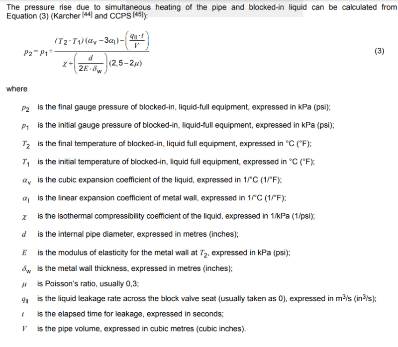
API 521 has an equation for pressure rise due to blocked in thermal expansion.

If a compressible liquid is trapped and heated, it will expand and it can/will break things if there's no provisions to relieve pressure/divert flow.
 
You mean this one?
api_skdbvt.png


But we would have to know the time for leakage, which we don't. Is there a way we can calculate or estimate a reasonable time?
 
@shvet, hes asking for the distance between PRV's.

@KFCeng, assume leakage is zero that would be worst case.


--- Best regards, Morten Andersen
 
MortenA said:
hes asking for the distance between PRV's.
KFCeng said:
But we would have to know the time for leakage, which we don't. Is there a way we can calculate or estimate a reasonable time?
 
This question arises a lot during design of plants etc and AFAIK, there are no formula or calculations I've ever seen, only company guidelines and procedures from the bigger companies or design houses or in design books like you quote. There is no real science behind it.

It is a mixture of practicality and cost to arrive at any length where you can say you don't need pressure relief. What that is seems to vary widely.
For me anything over 5m should have one, but sometimes you see this expressed in volume. The reality is that as pressure rises, valves leak / pass, flanges weep, seals pass and you often only need a small volume to greatly affect pressure.

I can remember walking around a fuel manifold in the sun thinking there was a leak, but the guages were all rigid at 100 bar and it was all the thermal reliefs gently hissing into the closed drain system.

Each to their own seems to be the rule, but remember pressure rise can be 2 to 4 bar per degree C rise. So start at a low pressure in a high pressure class system and you might be ok. Reverse and you won't. See this FAQ So if you can show that at your start temp and pressure and your final solar temp which is rarely reached, especially on larger lines, and you are within your design pressure then you are ok. But if not then you are at risk of exceeding your design pressure.

But also remember that any system which expands and relieves through a valve can then cool and go into vacuum / vapour generation mode....

Also remember some liquids expand a lot like LNG and LPG where you get huge volume changes.

You can never get this right. Too few and damage / leaks and potentially rupture can occur in locked in sections or they become difficult to open under high DP. Too many and everyone complains about the cost and the small bore drain pipes and maintenance costs increase.


Remember - More details = better answers
Also: If you get a response it's polite to respond to it.
 
You make your best guess during design. Then after startup and during operations, you tweak it.

Good Luck,
Latexman

 
KFCeng said:
but we cannot seem to find any.

You've answered your own question....

The problem with doing it later is that you don't have the tees or drains set up and you've made the valves leak...

The other option is to show lots of valves as NO or CSO to give you longer lengths with a thermal relief valve in normal operation, then procedures take over.

I've never been comfortable with relying on some basic guess from a procedure or guide, especially when some designers treat them not as guidelines, but as commandments from their god written on tablets of stone.

Remember - More details = better answers
Also: If you get a response it's polite to respond to it.
 
Are you considering all design options? TRV's are just one tool in the toolbox.
Expansion device/chamber.
Stand pipe with a gas (compressible). The poor man's expansion chamber.
Shelter/shade the area.
Insulation.
Using control valves (they leak) instead of ball valves.
Using control valves with lower leakage class.
Program valves to open momentarily based on inline PT's or during the heat of the day. Programming is easily tweaked.
Go through the design and try to minimize/eliminate the block valves.
I'm sure there's other options.


Good Luck,
Latexman

 
Is this tubing or piping you're dealing with ?
TRVs are required for any blocked in volumes where heat input can result in pressure rise beyond piping design pressure, no matter what the blocked in volume is - for piping. I dont know of such requirements for tubing.
 
ExxonMobil's std. XVC said:
6.12.3 Application of Liquid Thermal Expansion Protection
...
Short sections of piping less than 100 ft (30 m) in length but not exceeding 250 gallons (900 l) in volume which can be blocked in, generally do not need thermal relief valves.

Shell's DEP 80.45.10.11 said:
3.10.4 Piping
...
2. Piping that can be blocked in and contains more than 500 L of LPG or “very toxic” liquids require a TERV. For processes that have a low threshold on material releases (e.g. environmental reporting of ethylene oxide releases), more stringent criteria than what is shown above may be appropriate.
3. Other process lines shall have a means for thermal expansion relief, if all of the following conditions are met.
a) Line is completely full of liquid (i.e., more than 95 % full).
b) It is intended that the line will be blocked-in at both ends.
NOTES:
1. Is the piping or equipment continuously in operation and thus unlikely to be isolated without being depressurised and drained? Most process equipment and piping is in this category.
2. A check valve is considered an isolation valve in one flow direction when evaluating relief paths only.
3. The closure of valves that are used only for maintenance isolation (i.e., not a normally operated valve) is usually not considered a condition that requires thermal relief because it is expected that procedures to prevent liquid thermal expansion overpressure will be followed.
c) It is not practical to drain the line or to provide a thermal expansion relief path.
d) Line is above ground and will likely heat up due to solar radiation, heat tracing, etc.
e) The pipe volume exceeds 500 l.

JGC's std. 210-120-140 said:
6.9.1 Provision of Thermal Relief Valve
The guidelines to provide thermal relief valves are as follows:
(1) Thermal relief valves are not required for :
- process plant piping
- storage or transport piping sections which are not normally shut in for operational or emergency purposes
- lines in which there is normally a two-phase flow
(2) Thermal relief valves are needed for :
...
- sections of piping containing more than 0.5 m3 of LPG or toxic liquids which could be blocked in
- piping in storage areas or transport lines which will be regularly blocked in during normal operation, to protect against pressure rise due to solar radiation or heat tracing
- all sections of cryogenic piping (operating below ambient temperature) which can be blocked in
- piping around pumps which are operating at cryogenic temperature.

Total's std. GS EP SAF 262 said:
 
Status
Not open for further replies.

Part and Inventory Search

Sponsor