Continue to Site

Eng-Tips is the largest engineering community on the Internet

Intelligent Work Forums for Engineering Professionals

  • Congratulations SSS148 on being selected by the Eng-Tips community for having the most helpful posts in the forums last week. Way to Go!

Measuring bending using strain gauges 1

Status
Not open for further replies.
Dear All,
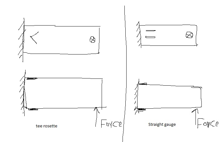
I would like to measure bending moment on tube without measuring all other forces and moments. I am planning to use four strain gauges to measure the bending using full bridges. I am little confused between using tee rosette strain gauges similar to this one and stick it on 45 degree or just use normal strain gauges.
There are forces and moments affects on the tube in all directions, but I want to measure only moment produced from one forces only as shown in the figure. I am not sure which approach is correct to measure the bending and neglect all other forces and moments. See the attached drawing.
Untitled_a2gudr.jpg

 
First: The straight gauge is what I would choose to isolate the bending in the given plane.

Second: Is your material isotropic and of known modulus of elasticity? If both of these things are not true, it will not be possible to accurately calculate the bending moment. Also, very accurate measurements will be required in order to achieve accurate results. Do not depend on as-ordered thickness for the tube, as there is a manufacturing tolerance.

Finally: Have you considered using a piezometric force/pressure sensor to directly measure the input force? This would allow you to isolate the bending moment more efficiently.
 
Many thanks for your answer. So, you recommend to use straight gauges not using tee rosette for measuring the bending. Actually, I will calibrate the strain gauges after I stick on the tube to find the relation between the bending moment and forces. I think in this case I won't be too much worried about material isotropic and modulus of elasticity. What do you think?
Also, I am wondering when tee rosette is recommended to be used.
 
I would use axial gauges on the cap surfaces, and rosettes on the sides

another day in paradise, or is paradise one day closer ?
 
If you rotated your T rosette 45 degrees then one gauge could be used to pick up poisson strain (giving you an additional 30% over one gauge). If you keep the T rosette positioned as is you could measure torsional stress.
 
I'd use a three channel rosette ... haven't used "T" configuration before. with three channels you can get principal stresses (and shear stress) ... maybe the "T" channels combine to give you shear stress ?

another day in paradise, or is paradise one day closer ?
 
Many thanks for you all. So, you say that this arrangement for tee rosette is good for torsional stress. What about if I put at 90 degree withrespect to axial axis? Also, can I say bending moment is kind of torsional stress or it is different.
At the end, based on your recommendations I will use two axial strain gauge to measure the bending moment and avoid using tee rosette
 
At 90 degrees, you could measure the axial strain and the poisson strain. A T type rosette would be useful if you want to measure strain in small area. If you have enough real estate then use 2 separate axial strain gauges. It will give you more output.

Remember when you complete the bridge to be careful on polarity and the position on the gauges in the bridge.
 
"can I say bending moment is kind of torsional stress" ... no, bending stresses are very different to torsional stresses.

personally I'd never use two axial gauges in lieu of a rosette (or T gauge) ... if the two aren't aligned perfectly, the results are misleading (at best).

Figure out what it is you want to measure ... bending stress is best measured on the upper and lower surfaces, the gauges on the sides won't detect much bending (being near the NA), is shear on the sides a concern ?

another day in paradise, or is paradise one day closer ?
 
Mawad:
And, if you’ve never used or applied strain gages before, don’t assume that’s a piece of cake just because you’ve read a page or two about strain gages. As usual OP’ers. rarely give enough meaningful info. about their problem, so as to minimize the amount of guessing and imagining that we have to do, in trying to be helpful. Just for the fun of it, since you’re the one wanting help, and we’re the ones wasting our time to try to do that, why don’t you provide a sketch, to scale, of your cantilever? Material thicknesses and sizes, loads, and how you intend to provide fixity at the left end, including welding, bolting, etc. If that thing is a 2"x2" sq. tube and 6" long, it will act quite differently than a 10"x12" stl. tube that’s 6' long, even though they are both cantilevers. Also, tell us what you are really trying to prove. If you really wanted to see something interesting, use 3 straight gages t&b. One on the center line and the two side gages equal spaced and out near the corner radius of the tube; this first line of gages within a couple inches of the fixed end pl. Then move out 6" or 12" on the beam and repeat this gage arrangement again, and maybe again at another beam length interval. Tell us what you think this might show. Don’t someone else answer this for the OP’er., let him explain what he would expect to see.
 
dhenger,
I don't have experience with using strain gauges. I haven't completed the design yet as I am gathering information about the strain gauges to use them correctly. I want to build walking robot and I want to use strain gauges on the shank to measure the bending moment in the knee flexion extension direction due to the forces coming from the ground to get indication about the direction of the forces to prevent bucking and also measure the vertical force in the shank. I want to measure them only, but all forces and moments comments will be affecting the leg while walking. I want to cancel all these forces/moments, so I decided to use full bridge to cancel all of these components for the bending and half bridge for vertical axial load. I will use two straight gauges one on each side to build half bridge. However, I confused about the gauges for the bending either to use four straight gauges or two Tee rosette. I thought Tee rosette may be good option to cancel all the forces and moments and keep only the one that I want according to its orientation. This why I was asking. This is my application. I haven't decided yet about the shape of the structure which I will stick strain gauge on it, but I was thinking about using Aluminum cylindrical tube for the shank. I tried to find online material for proper information helping in design and calculation of such such systems using strain gauges, but I find very little information. Do you suggest some good material helping me in that.
Kind regards
 
I remember seeing strain gage setups on bicycle frames when they were experimenting with carbon fiber tube frames. Maybe some ideas and resources there. Sorry I didn't save the websites.
 
measuring a robot leg is quite different IMO to the sketch provided (which suggests a simple cantilever).

if the leg is slender (like a bicycle tube) then 4 axial gauges at 90deg would probably be enough.

if the leg is bulky (like a square box, with 4 faces) then I'd use 4 rosettes.

I'd also calibrate the gauges by testing the leg with known loads.

another day in paradise, or is paradise one day closer ?
 
In the last post you mentioned you wished to learn more about the correct use of strain gauges in a structural test. Looking at your sketch, long before you decide on what configuration of strain gauges to use you first need to understand the purpose of testing. The purpose of most testing is to validate your analysis work. So your test setup needs to represent the conditions used for your analysis as closely as possible. This would include how the part is restrained and how the loads are applied. The relative stiffness of the attachment structure and kinematics of the device applying the load can have a significant effect on your test results. If your test setup does not accurately represent your analysis case, then the test data will be of no value.
 
Status
Not open for further replies.

Part and Inventory Search

Sponsor