Eng-Tips is the largest engineering community on the Internet

Intelligent Work Forums for Engineering Professionals

Measuring line profile and basic dimensions

Status
Not open for further replies.

Rob J

Mechanical
Mar 6, 2024
5
0
0
US
One of our suppliers reported back a line profile that indicated the part was good. However on further measurement I found one edge was wrong. That edge has a bunch of angled faces with multiple radii. So I did not add any basic dimensions as it would have really clutter the drawing. The metrology lab from the supplier stated they only measure the basics for the line profile and report back whether all the basic dimensions meet the tolerance defined in the line profile.

From my understanding:
"Profile of a line is measured using a gauge that is referenced to the true profile at the given specific cross-section. Because there are an infinite amount of 2D cross-sections of any part, the number or locations of measurement points can be specified on the drawing."

The part that gets me is the second part which states the number or locations of measurement points can be specified. But is doesn't state that the basic dimensions are those defined points.

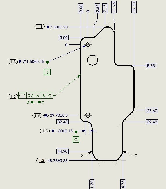
Do you have to put any basic dimensions on a view where a line profile is called out?
Can you just put points along the profile of where you want them to measure but not actually put basic dimensions?

What is the correct way to ensure the supplier understands that a line profile is the entire profile and not just the few basic dimensions on the print? And I do have the circle on the line to indicate all the way around.

Any insights and opinions would be greatly appreciated.
 
Replies continue below

Recommended for you

It sounds like there is some confusion on the part of everyone involved.Let's start with this:

"The metrology lab from the supplier stated they only measure the basics for the line profile and report back whether all the basic dimensions meet the tolerance defined in the line profile."

They shouldn't report any basic dimensions, but rather the value that quantifies how accurately the actual feature elements fall into the profile of a line tolerance zone.
 
Hi, Rob J:

Profile of line has no meaning until you define its associated BASIC dimension.

BASIC dimensions are not specifications by themself. They are for CMM programming purpose. The inspector needs to report measurement for this Profile of line.

Best regards,

Alex
 
Hi Alex,

So if I have an highly complex curved part that I want to know the profile of I need to provide basic dimensions? Would I define several points along the curvature? Seems to me that line profile makes the drawing and measurement more complex than simplifies. I can see where adding insufficient basic dimensions will only lead to error in calculating the line profile.

And for clarification the supplier only reported back the line profile tolerance measurement. Which indicated the part was meeting specification per the print. But it is because they only "used" the basic dimensions on the print to define the profile. Which in effect missed areas in between defined points.

So if you have a straight line (this is just a thought example) and you want the profile of that line. Would you define just the beginning X,Y and the end X,Y? Or would you need to define several points in between? If the inspector only measures the start and end and reports back that the line profile is good and the part has a bow in the middle how would I know from the reported measurement?

 
"Seems to me that line profile makes the drawing and measurement more complex than simplifies."

Either you want to control the surface or not. If you want to control it you need to describe the nominal surface and the acceptable amount of variation from that nominal surface the as-manufactured part surface can have.

If the nominal surface is complex then, typically, the dimensioning of the nominal surface will also be complex.

"But it is because they only "used" the basic dimensions on the print to define the profile."

Those are the only description of the nominal surface and are the only basis from which to make measurements.

"So if you have a straight line (this is just a thought example) and you want the profile of that line. Would you define just the beginning X,Y and the end X,Y? Or would you need to define several points in between? "

The dimensions and the geometry define the nominal surface; they work as a group. The sampling along the nominal straight line depends on how much confidence there is that the result will represent the actual result. Maybe the tolerance zone is a half inch wide and you can't see a gap with a straight edge on it. Pretty clear it meets the requirement and all that is required may be the ends. But if the tolerance zone is 5 nanometers then maybe sampling at 20 nanometer intervals is called for.

No inspection is perfect and, particularly with CMMs, it is not possible to sample every bump on every atom on every crystal in a metal part; taking reasonable samples is a judgement call that needs some justification.

" I did not add any basic dimensions as it would have really clutter the drawing. "

If there aren't basic dimensions then there should not be a profile tolerance to inspect.

Since we don't know what you did or what they did, getting more specific is not possible.
 
Hi, Rob J.:

Your print should show your design intents regardless how the part is inspected. If you have a line, then you need to define it with dimensions and profile tolerances. You don't have to show BASIC dimensions for the line on your print. For example, if your 3D model is accurate, you can add a note to indicate features without dimensions are BASIC per 3D model. This essentially authorizes your vendor to poke the 3D model to get "those" dimensions that are not shown on the print.

You can also do MBD for parts without prints. You will need to follow ASME Y14.41-2003 "Digital Product Definition Data Practices", or you can create your own standards.

Best regards,

Alex

 
Adding to what jassco mentioned about referencing the 3D model for basic dimensions, below the profile tolerance feature control frame you could specify with letters the area where along the edge the profile is to be controlled, like between X and Y. You could also put a flagnote there and in the general notes it would say something like "Refer to 3D model for basic dimensions."
 
Thanks for all the feedback and help.

Currently the drawing general notes states "Refer to 3D model for Dimensions". And I have defined the points along the line I want measured. And I provided the basic dimension of where the start point was and the end point. But the vendor only measured those two points and reported back that line profile was in spec. But once I received the parts and did my fit check I found an edge of the part that was not matching the CAD. Hence the line of questions. I am now adding a plethora of basic dimensions on my print to indicate all the areas I want them to use in calculation of the line profile.

I really thought line profile would be measured by importing the outline of the CAD model, offset the lines at the given tolerance range, and then see if the perimeter of the actual part fell within that boundary. But I'm seeing from the responses above that line profile is a bit more nuanced and requires clear basic dimensioning (even with complex curves).
 
The features of the model are usually consider basic if the model is to be used as a reference. You don't appear to have a dimensioning problem, you have a vendor problem and need to ask why they didn't check the tolerance given.

My sneaking suspicion is they did check it, found it out of tolerance, and decided to only report those points that were in tolerance and hoped you would either not notice or would eat the problem.

Maybe there is something about the drawing that puts the blame on you, but so far it isn't reasonable to ignore the entire edge.

First, of course, is whether you sent them the related model. If so you can ask if they used it in the CMM software and then ask to see the CMM program portion that covers this feature (go for broke and ask about all the features.)
 
That looks clear enough. The tolerance applies to the part between X and Y, so all of the (roughly) 19 segments that are in between should be inspected.

Line_Profile_view_ex92cf.jpg
 
That's what I would have thought. But they just checked each discrete Basic point and if that measurement met the +/-0.25 (0.500 profile tolerance) they reported back the line profile was good. But it turned out there was a defect in the part along one of the segments that interfered with the assembly. My next option is to add additional basic dimensions at multiple points along each segment.

It's definitely a vendor issue. And getting them to understand their mistake is a challenge.
 
Hi, Rob J:

It sounds like your vendor does not know what "BASIC" in the basic dimensions (dimensions with boxes) means. "BASIC" dimensions are not specifications. Your vendor is not supposed to report those BASIC dimensions. Your specification is a 0.5mm profile of line wrt datum A, B, and C.

Do you know if your vendor has a CMM machine?

Best regards,

Alex
 
MANDATORY APPENDIX I REASONS CHARACTERISTIC IDENTIFIERS SHALL NOT BE APPLIED TO BASIC DIMENSIONS
I-1 CHARACTERISTIC IDENTIFIERS SHALL NOT BE
APPLIED TO BASIC DIMENSIONS

Characteristic identifiers shall not be applied to basic
dimensions for the following reasons:

(a) Basic Dimensions Do Not Represent Variable Characteristics
of an As-Produced Part. Basic dimensions represent
constant values that define theoretically exact
geometry. Basic dimensions do not define variable characteristics.
Characteristic identifiers shall be assigned only
to characteristics that are variable.

(b) Chained Basic Dimensions With Characteristic Identifiers
Applied Will Create Confusion. If chained basic
dimensions are used to define true position or true
profile, it is not clear which basic dimension should be
assigned a characteristic identifier, or why one basic
dimension in the chain should be selected to receive a
characteristic identifier when another is not. To choose
one basic dimension within a chain would be arbitrary.

(c) Some Basic Dimensions Are Not Shown. A basic
dimension that is a distance or angle with a value of
zero, or an angle that is any multiple of 90 deg, is not
shown. When model-based definitions are used, no
basic dimensions are shown. Basic dimensions that are
not shown cannot have characteristic identifiers.

(d) Basic Dimension Numbering Is Not Clear When
Several Features Share a Common Center or Common Location.
If several features are aligned such that they share the
same basic dimension, it will be difficult to make it clear
which characteristic identifier goes with which feature.

(e) Grouping of Data for a Particular Tolerance in a
Report Is Achieved by Applying Characteristic Identifiers
to the Applicable Tolerance, Rather Than to the Basic
Dimensions. If basic dimensions have characteristic identifiers
applied, then data for the associated location
components or surface deviations may not be grouped
in the report with the data for the tolerance that they
serve.

(f) Some Feature Geometry Cannot Be Defined With
Explicit Basic Dimensions. For more complex cases,
basic dimensions cannot be identified in any way that
will lead to sensible data. Examples are shown in
Figure I-1.

ASME Y14.45-2021
 
Since you are already relying on CAD model, just omit any 'points' along the path and force them to choose. If they ask which points they need to measure to know if the part is acceptable, then fire them. "Which dimensions are critical to meet specification? [ponder]" "All of them" [flame]
 
3Ddave said:
Fire them.

Yes, that is an option, but might not be the most efficient one.
New supplier, new approvals, new relationship.
Not sure if the EDUCATION is not a better option, but I guess also depends by their (supplier) attitude and how open they are to pertinent feedback.
 
Status
Not open for further replies.
Back
Top