Continue to Site

Eng-Tips is the largest engineering community on the Internet

Intelligent Work Forums for Engineering Professionals

  • Congratulations pierreick on being selected by the Eng-Tips community for having the most helpful posts in the forums last week. Way to Go!

Measuring Output pressure

Status
Not open for further replies.

istoodent

Mechanical
Sep 18, 2019
1
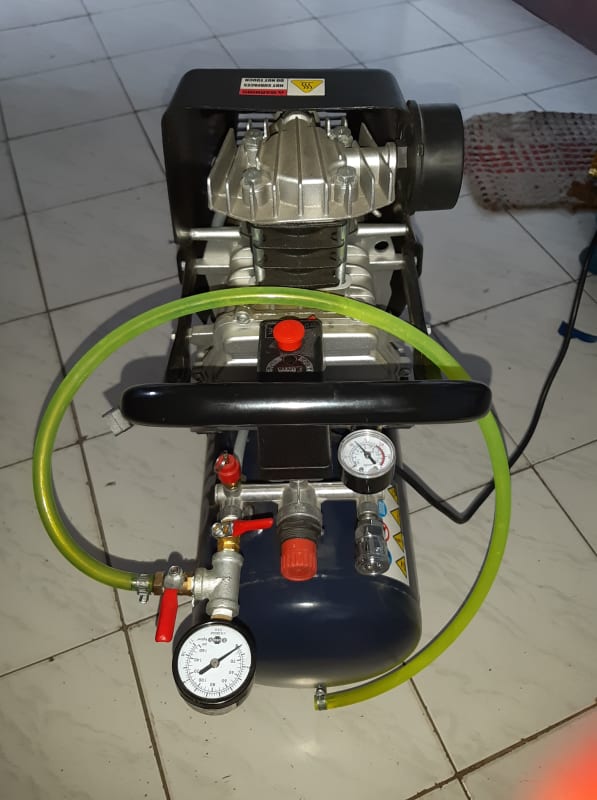
Hi im a student trying to control/set the pressure of air going out of our air compressor, the air compressor has only one gauge for the tank and we're trying to control it by installing a valve and another gauge to read the output. is this correct?


70498471_395840311129021_8572496994713468928_n_ptlyh4.jpg
 
Replies continue below

Recommended for you

Why is outlet pipe connected (green hose) back to tank? The downstream (outlet) gage will read lower than the tank pressure depending upon the regulator valve setting.

Walt
 
The outlet isn't connected; a zoom of the image shows the hose clamp touching (maybe) the tank, but there is typically no connector to the tank located there.

What you show is one possible way of doing it, although most configurations only have a single valve.

TTFN (ta ta for now)
I can do absolutely anything. I'm an expert! faq731-376 forum1529 Entire Forum list
 
IRstuff,
Good catch with image zoom showing hose end is NOT attached to tank! The regulated pressure output looks to be at the quick-connect coupler. The hose looks to be connected directly to tank pressure and in-line with pressure relief valve. I would not run my compressor with this hose connection scheme, since there is no regulator control!

Walt
 
I also believe regulator is in middle (red knob). I believe tank connection is at left where relief valve (red knob) is located. Typically a small air compressor like this one has two pressure gages; one for tank pressure (at left) and one for regulated output pressure (at right). Perhaps the OP can indicate why the output hose is connected directly to tank pressure and not to the regulated output quick-connect coupler. If the manifold is connected to tank on left side, then I would connect the pressure gage (left one) directly to the relief valve, and move the shut-off valve and output hose over to the quick-connect coupler (with adapter) on the right side.

Walt
 
Hmm, my impression is the exact opposite; the gauge on my right is the tank pressure, which is showing a non-zero value, then the air goes left through the regulator, through a first shutoff valve, through the second gauge, which is showing zero pressure, through the output valve, and finally out the flex hose. The gray hose behind the relief valve doesn't make much sense. But, typically, you would not have a flex hose coming from the tank, since it has the highest pressure and all the plumbing up to the final valve is typically solid metal.

TTFN (ta ta for now)
I can do absolutely anything. I'm an expert! faq731-376 forum1529 Entire Forum list
 
IRstuff,

If you expand the photo, it looks like the tank connection is on the left size directly under the pressure relief valve (red hat with metal ring and pin). I could be wrong, and this is getting to be a waste of time!
Walt
 
Status
Not open for further replies.

Part and Inventory Search

Sponsor