Eng-Tips is the largest engineering community on the Internet

Intelligent Work Forums for Engineering Professionals

Medium Voltage Distribution Issue 1

Status
Not open for further replies.

RonUH

Electrical
Mar 31, 2023
10
0
0
US
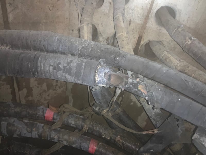
I work at a large University in Texas. When the electrical deregulation happened here the utility built us our own 138kv/12,470kv substation. Ever since we have had issues with our concentric neutrals burning up on our pole tops and splices burn up in our manholes every few years.

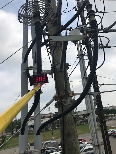
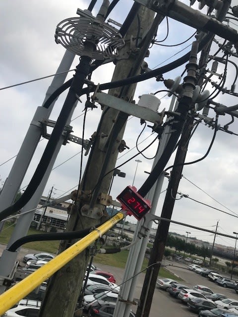
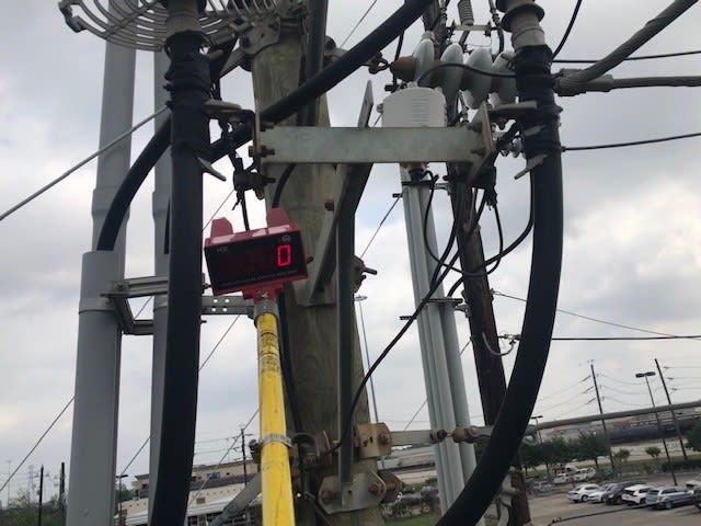
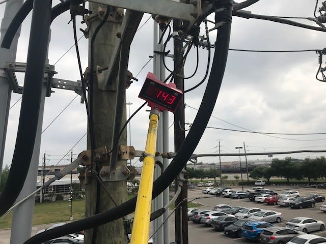
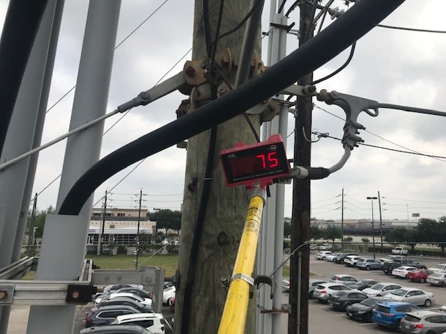
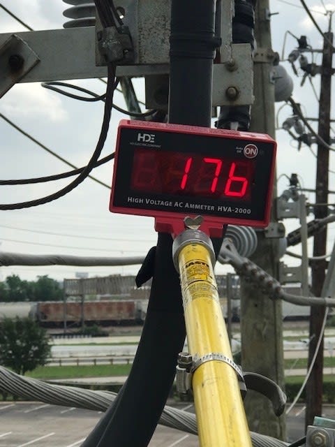
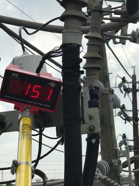
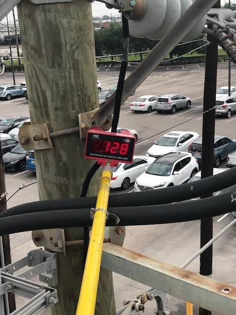
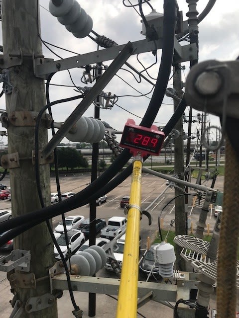
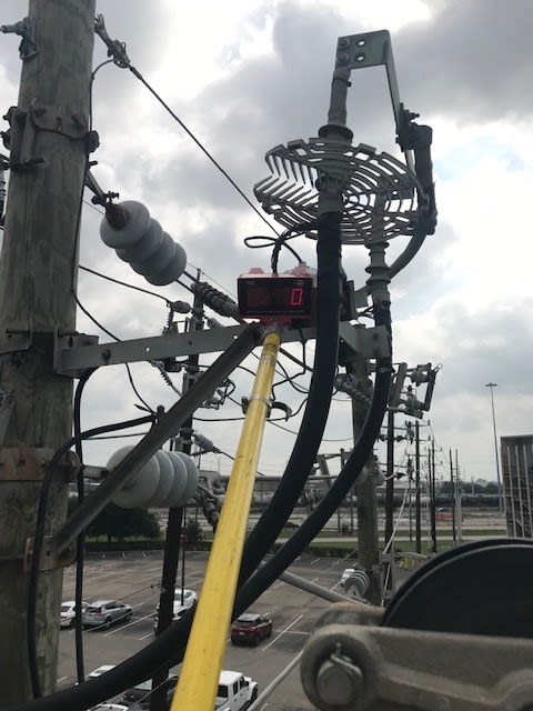
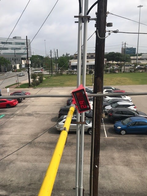
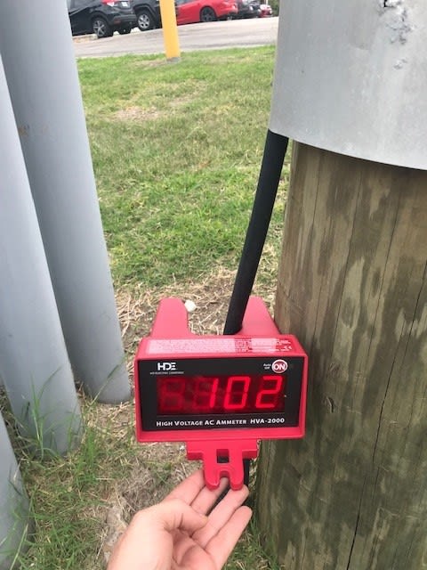
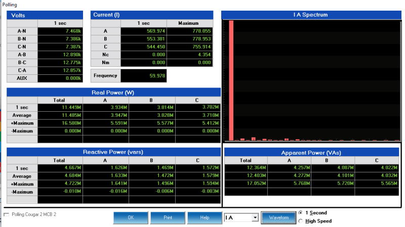
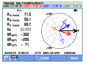
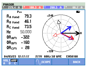
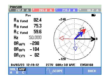
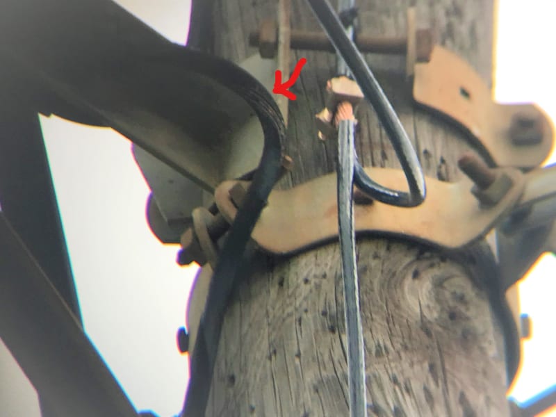
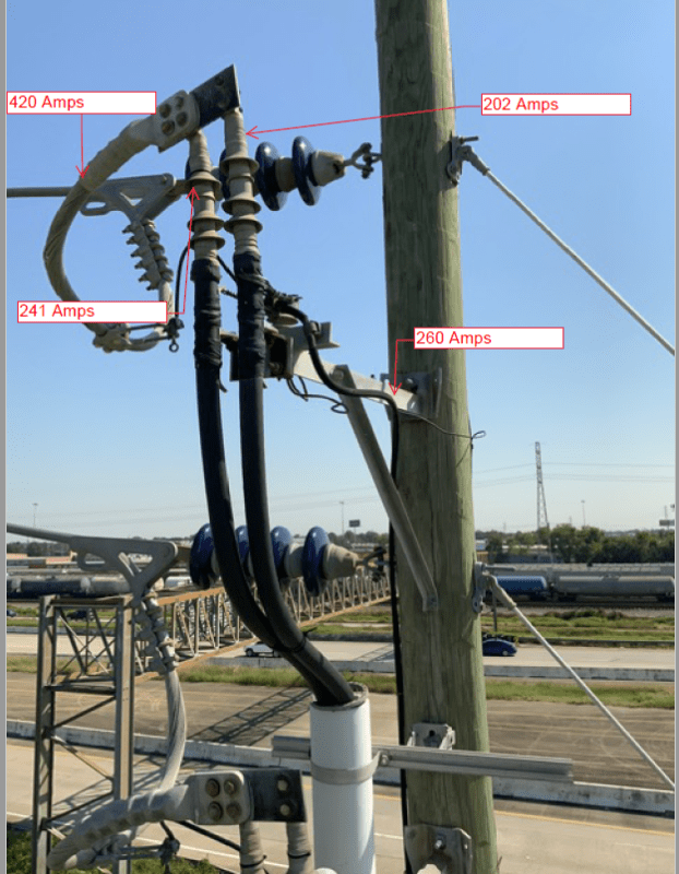
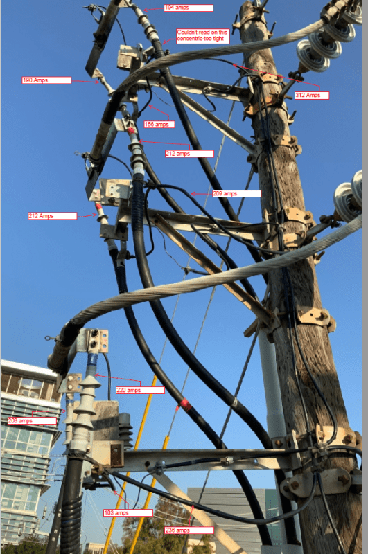
Although my SEL relays only show about 25amps of neutral current, I have measured 200 amps on the pole top jumpers between the concentric neutrals on the cable to the main neutral cable. See attached pictures for examples of the very strange readings.

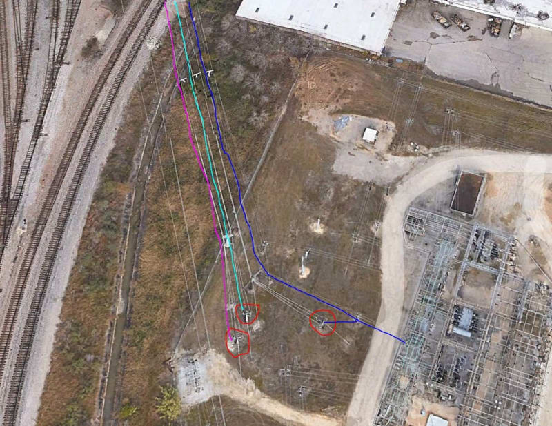
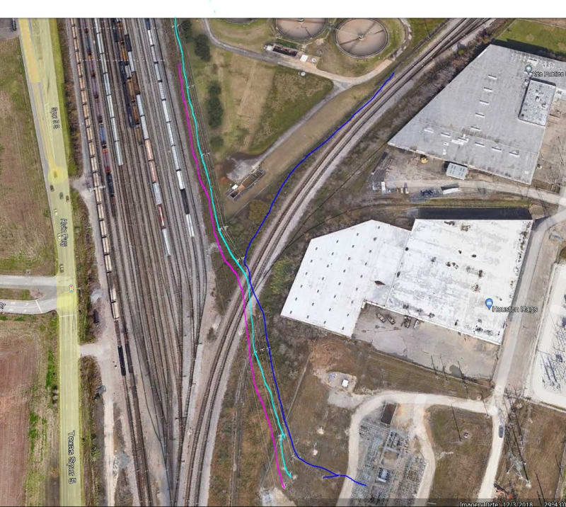
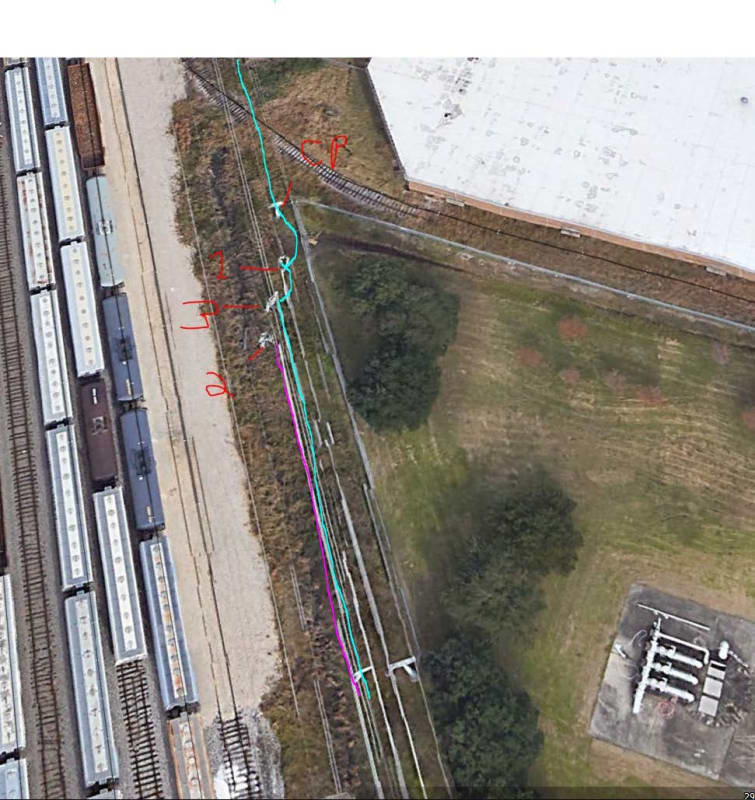
I recently walked the line and noticed there are still some interconnections between our circuit's neutrals and the utility company (Center Point) city circuits that all originally came from the utility substation that these circuits used to originate in. Could this cause circulating neutral current at these levels?

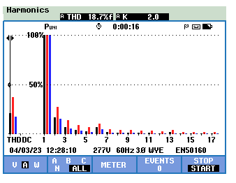
The SEL relay also does not show excessive harmonics.

These are our main feeders from our substation Delta/Wye 138/12 KV transformer to our main gear on campus which connects to a ring bus. Entire run is about 1.1 miles from Sub to Central Plant. Some underground, some overhead.

We have 3 circuits, 2 of which feed a Main tie Main gear. 1 of which normally only feeds our Central Plant. The 2 that go to the main tie main gear each break out into 8 sub feeders which power our campus buildings. The Sub feeder cables do not have concentric neutrals tape shield only.

I should also mention that our incoming Main Feeders have a Nexus 1500+ power quality meter and although they do not have neutral CT's installed the meters do not show any calculated neutral current. But if I put an amp probe on the concentric neutrals at the back of the gear i can read up to 200 amps.

Anyone ever see this before? Any ideas?
CGR1_Spur_c30gvm.png

CGR1_nw6iex.png
URL]
URL]
 
Replies continue below

Recommended for you

I don’t have a ton of experience with dealing with neutral current, but the experience I have had made me conclude it can very complicated, especially as you say that neutrals are tied to other sources.
One technique we tried to use was to determine the phase angle of the neutral current relative to say phase A to see if we could rule anything out by the phase of the current.
I would also look at the transformer configurations and make sure your neutrals aren’t providing a path for other ground sources. You also might ask the utility if they have unbalanced feeders. Sorry this isn’t more helpful, good luck!
 
Would you please tell us whether your 12.47kV distribution is 3Ph/ 3Wire or 3Ph/ 4Wire.
If it is 4Wire then could you please mention
1) How & where the 4th wire is terminated?
2) Does the 4th Wire consist of the concentric neutral of 12.47 cables or otherwise?
 
Are you seeing a corresponding ground current anywhere?
Are the concentric neutrals grounded at both ends?
You may have induced EMF in the concentric neutrals which is shorted out by grounding at both ends.
Even a relatively low induced voltage in a sheath or concentric neutral will drive a relatively heavy current through a closed loop.

--------------------
Ohm's law
Not just a good idea;
It's the LAW!
 
We did an installation of multiple single conductor cables from a generator to a transfer switch.
We used single conductor TECK cable which incorporates a concentric equipment grounding conductor that is a similar construction to a concentric neutral.
The concentric conductors were grounded at the supply end and taped off and insulated at the load end.
This was done to avoid the possibility of induced current circulating in the concentric conductors.
An external grounding conductor was used.


--------------------
Ohm's law
Not just a good idea;
It's the LAW!
 
Unless you have an unusual connection of the relay, the "neutral" current on the relay is the residual current of the three phase currents. If that's that case, anything that's on the neutral than isn't unbalanced return from single phase loads isn't going to be seen by the relay.

I’ll see your silver lining and raise you two black clouds. - Protection Operations
 
David; Will the I[sup]2[/sup]R loss resulting from the circulating current show up as slightly higher line currents?
Thanks.

--------------------
Ohm's law
Not just a good idea;
It's the LAW!
 
No idea, but if it did it would be indistinguishable from normal load.

I’ll see your silver lining and raise you two black clouds. - Protection Operations
 
I think you are on to something with possible circulating currents from the utility neutrals. I'd inspect the utility neutrals to see if there is an open point somewhere that is forcing utility neutral current to flow through two points on your neutral. This could be severe during a utility ground fault, causing thousands of amps of fault current to flow through your concentric neutrals.
 
Thanks for all the replies. I will attempt to address all the questions below:

wcaseyharman said:
One technique we tried to use was to determine the phase angle of the neutral current relative to say phase A to see if we could rule anything out by the phase of the current.
I would also look at the transformer configurations and make sure your neutrals aren’t providing a path for other ground sources. You also might ask the utility if they have unbalanced feeders.
No sure what you mean by " Path for other ground sources." Our substation transformers (2-33 MVA) are 138kv Delta to 12.470KV Wye.
They leave our substation underground to the Utility substation that the circuits used to originate from before our sub was built.
Then it transitions to overhead for about 1/2 mile.
Then it goes underground again for about 7,000 ft.
Transitions to overhead again for about 300-400 ft.
Transitions to underground for the remaining 1100 ft to the back of our gear.

Cable is parallel 1,000 MCM with 1/3 concentric neutrals. All concentric neutrals are bonded in each manhole and on overhead.

Kiribanda said:
Would you please tell us whether your 12.47kV distribution is 3Ph/ 3Wire or 3Ph/ 4Wire. I guess that depends if you consider the Concentric neutral as a wire. Since it is a Delta Wye transformer and the cables have a concentric, I would consider it a 4 wire.
If it is 4Wire then could you please mention
1) How & where the 4th wire is terminated? The Concentric is terminated at every terminal pole and every manhole to ground.
2) Does the 4th Wire consist of the concentric neutral of 12.47 cables or otherwise? It consists of both, where it transitions to overhead, there is a separate 2000 MCM cable. But as mentioned in the original post there are strange interconnection with CenterPoint city circuits so there is NOT 1 Neutral for all these circuits.

waross said:
Are you seeing a corresponding ground current anywhere? Not much, a few amps at most as measured by the SEL relay.
Are the concentric neutrals grounded at both ends? Yes, and at each manhole and terminal pole.
You may have induced EMF in the concentric neutrals which is shorted out by grounding at both ends. I know we do have some issues with induction due to the way the Utility originally ran part of the underground. Instead of ABC in one conduit for each parallel run they ran 2 A's and a B or 2 C's and a A. Really strange stuff. We have corrected one of the 3 runs. Are you saying that the concentric should NOT be bonded at all points?

Even a relatively low induced voltage in a sheath or concentric neutral will drive a relatively heavy current through a closed loop. So, are you suggestion disconnecting the ground connection at one end?

davidbeach said:
Unless you have an unusual connection of the relay, the "neutral" current on the relay is the residual current of the three phase currents. I believe that is the case, It was wired according to the SEL diagram. If that's that case, anything that's on the neutral than isn't unbalanced return from single phase loads isn't going to be seen by the relay. I am not sure what you mean here. We only have 1 small 7200/240 transformer on campus.

jghrist said:
I think you are on to something with possible circulating currents from the utility neutrals. I'd inspect the utility neutrals to see if there is an open point somewhere that is forcing utility neutral current to flow through two points on your neutral. This could be severe during a utility ground fault, causing thousands of amps of fault current to flow through your concentric neutrals. Yeah, I wish it was easier to explain the strange connections I have seen.

See below pictures for how the Neutrals are connected on CGR 1,CGR2 and CGR 3. Each different color is a different neutral conductor. CGR 2 is the reddish line. Aqua line is CGR 3. Dark Blue is a CenterPoint circuit.
The terminal pole in the CP yard is tied to a neutral on a CP circuit.
The CGR 1 neutral at terminal pole by the railroad is tied to the CGR 3 Neutral and also jumps to a different CP circuit and continues down the line.


CP1_Overhead_Neutral_connections_li3pmk.jpg
CP_2_Overhead_Neutral_connections_lklcrd.jpg
RR_1_Overhead_Neutral_connections_ygm1jc.jpg
 
So, the pics in the original post were on circuit CGR1. That is the circuit that had a splice failure again on 3-15-23, so all building loads have been on circuit CGR2. The following pics are form readings this morning.

1_omioet.jpg
2_iu6oth.jpg
3_xwj0hg.jpg
4_gszghk.jpg
5_wialco.jpg
6_snyzcm.jpg
7_pztgxi.jpg
8_gjvloz.jpg
9_tavn3o.jpg
10_tmhpn5.jpg
11_c2cw25.jpg
12_slrrbo.jpg
CGR2_Harmonics_at_pole_wdnoer.png
CGR2_Nexus_4-3-2023_qiphsb.png
CGR2_Set_1_uh1tto.png
CGR2_Set_1-1_pkvqhi.png
CGR2_Set_2_g7ss6w.png
 
A concentric neutral on a single conductor cable will mimic a shield.
It is common practice to ground shields at only one end.
You may be able ti greatly reduce or eliminate the unwanted current by transposing the concentric neutrals.
At each transposition, the load end of the A phase neutral is cross connected to the feed end of the B phase neutrl.
Then B to C and C to A.
Each neutral should spend an equal distance with each phase, or as near to equal as possible.
The neutrals must be isolated from each other and from ground at each transition.
That will allow the induced voltages to cancel out and with the induced voltages cancelled, there will be no induced current.

As for ground currents:
1. That is too much ground current to be reasonable.
2. You have a textbook case for circulating currents from induced shield voltages.

--------------------
Ohm's law
Not just a good idea;
It's the LAW!
 
I too believe the current is armour or shield current and not exactly neutral current and this is induced current in the shield due to earthing of shield (armour) at both ends of the cable.
 
Waross, Thanks for the input.

waross (Electrical)4 Apr 23 01:54 A concentric neutral on a single conductor cable will mimic a shield. It is common practice to ground shields at only one end. [COLOR=#F57900 said:
I understand that it may mimic a shield, but it is not just a shield. It is a neutral. From what I have been reading, it is common and accepted practice to do it this way.
and : [url=https://peguru.com/2012/12/power-cable-neutral-and-system-grounding/]Link
[/color]

You may be able to greatly reduce or eliminate the unwanted current by transposing the concentric neutrals.
At each transposition, the load end of the A phase neutral is cross connected to the feed end of the B phase neutral.
Then B to C and C to A.
Each neutral should spend an equal distance with each phase, or as near to equal as possible.
The neutrals must be isolated from each other and from ground at each transition.
That will allow the induced voltages to cancel out and with the induced voltages cancelled, there will be no induced current.
There are multiple transitions from underground to overhead and back again. The overhead only has a single neutral to connect to. So, on a terminal pole there isn't a separate Feed/Load concentric. (Overhead is single 2000MCM phase conductors whereas the underground is Parrell 1000 MCM) What would the overhead static ground/grounded side of surge arrestors/terminal pole ground, connect to? The Concentrics are also bonded to the manhole grounds in each MH. Are you saying all these should be disconnected?

As for ground currents:
1. That is too much ground current to be reasonable. Agreed, we have had many splices blow up at the concentric snap ring and melted insulation from the jumper wires to prove that.

CGR1_MH-2A_v3ldxq.jpg

CGR1_DipPole_pic_2_2__LI_002_nwyddv.jpg


2. You have a textbook case for circulating currents from induced shield voltages. I don't disagree, but is there a possible solution other than a complete redesign of the existing system?

I really appreciate all the input.
 
Step one:
Interrupt the current.
At every access point, the concentric conductors should be grounded on the outgoing cables and insulated on the incoming cables.
A concentric wrap on a multi conductor cable may be a concentric neutral.
A concentric wrap on a single conductor cable is an equipment grounding conductor.
The concentric wrap may only be used to ground equipment that does not have the neutral bonded to the equipment.
When the concentric conductors are not used or can not be used for equipment grounding they should be treated as a shield and grounded at the feed end and isolated/insulated at the load end.
It is good practice and safer to treat each individual section independently and ground and isolate at each manhole or transition.

Step two:
Provide a neutral.
Is a neutral needed?
If all of your loads are line to line, you may not need a neutral.
If you do need a neutral there are several possibilities;
a) Run neutral cables with the phase cables. In some instances this is the easiest solution, but in your case this may be the most difficult and expensive.

b) Install an artificial neutral. This may be a zig-zag transformer or a small wye delta bank.
The zig-zag may be a special order. You may be able to use distribution transformers in wye/delta connection to develop an artificial neutral.
The size of the artificial neutral should be the greater of;
i) Adequate to carry the greatest possible neutral load current.
ii) Adequate to withstand fault current until the protection clears. This may be mitigeted by resistance grounding.

c) install a ground grid including consideration of a buried conductor encircling the buildings that are fed from the circuit.
This should be about three feet from the outer walls.

My first choice would be option b), artificial neutrals.

Note. Some literature designates the concentric conductors as a concentric neutral. Some literature designates the same construction as an equipment grounding conductor.
In the instances where the literature calls the concentric conductors a concentric neutral; Do you believe everything that a salesman tells you?
If so, this may not be the only disappointment in your life. grin
Comparing a four conductor cable, a three conductor cable, a two conductor cable and a single conductor cable,
When all phases of a circuit are inside the concentric conductors, the concentric conductors may be used as a concentric neutral (Ampacity permitting).
With a single conductor cable, even though the construction is similar to multi conductor cables, the concentric conductors may be used for equipment bonding but not as a neutral conductor.
Don't believe everything that the sales brochure tells you.

--------------------
Ohm's law
Not just a good idea;
It's the LAW!
 
waross,

In North America, it is very common for utilities to use a concentric neutral for underground distribution. The concentric neutral serves both as a neutral conductor and as an insulation shield. Single phase lines will have concentric neutrals with the same capacity as the main conductor because most of the return current flows through the neutral. Three phase circuits will commonly have a 1/3 or 1/6 size concentric neutral because only the residual current flows in the neutral and there are three concentric neutrals to share the current.

Since the concentric wires (normally several copper strands) act as the neutral, they must be carried through at joints to make a continuous path. One end cannot be isolated.

There will be current induced in the concentric neutral from the phase current, and this will reduce the ampacity of the cable because of the heating. This induced current will not be at the level measured by the OP. I would expect about 20A current induced with 200A of phase current.

OP,

I would try to remove all connections between the Center Point distribution system neutral and the university distribution system neutral. You will have a connection from the substation ground grid to the Central Point transmission shield wire which eventually gets connected to their distribution neutral, but a single point connections will not result in your neutral carrying the Central Point neutral current.
 
Mostly I agree with you, jghrist. This however is an extreme case, and is causing damage.
I understand that utilities, when using single conductor cables for three phase circuits, often transpose the neutral or shield connections at equal intervals to cancel induced voltages and sheath or concentric neutral currents.
Have I been misled?


--------------------
Ohm's law
Not just a good idea;
It's the LAW!
 
I had trouble interpreting the phaser plots, it’s wasn’t clear to me which label was associated with each phaser.

At my utility I believe the all the individual neutrals are bonded at each termination and grounded to the vault. I haven’t heard of any MV cable neutral transpositions, but when I am back in the office I will look through the design standards and see if there’s anything about that.
We did have a weird event maybe a year ago when a communication cable caught fire. The theory was the messenger wire was in parallel with the feeder neutral and the thought was there was a bad utility neutral connection that caused the neutral current to flow in the messenger wire. It got so hot it caught the comm cable on fire.
I think we (the utility) redid the neutral connections and the problem went away (this was overhead construction). That particular circuit was pretty imbalanced, I think it had close to 100A in the neutral.
I probably would check whether the utility had significant imbalance in their distribution circuits and if so, see if you can perform a test by getting a utility outage and measuring the neutral current at that time (I expect this outage would need to be in the middle of the night or something). If that confirms that the utility neutral current is flowing in your neutrals, I would look at severing the neutral connections first. I would do it carefully - if the utility has bad neutral connections, there could be significant voltage that will develops when the last connection is removed. You may consider doing the work during an outage.
I think I would try testing if the utility neutral current is flowing on your system first before rearranging the neutrals to prevent circulating currents as it seems to me it would be easier to verify or rule out.
Just my 0.02$


RonUH,

There is a lot of information in your posts and it would be really helpful if you could possibly insert the details onto a schematic which includes the neutral grounding locations and any ring arrangements. It might provide a better presentation to allow the problem to be assessed more thoroughly.

Like wcasey, I’m also having difficulty reconciling your phasor plots. The real and reactive power values seem reasonably balanced between phases. The phasor values are less clear however.
1. Are the "open triangle" arrowhead phasors displaying current magnitude and angle? They are close to 120 degrees apart but with some variability.
2. What are the "line" arrowhead phasors showing? – They are certainly not 120 degrees apart

Finally, the site is adjacent to rail tracks and although I cannot see traction power structures in the images, there does look like a line above the right most track. Is there any chance that there is traction power in the area? If so, it might be worth considering whether traction return currents could be carried in your neutrals.

 
jghrist said:
OP,

I would try to remove all connections between the Center Point distribution system neutral and the university distribution system neutral. You will have a connection from the substation ground grid to the Central Point transmission shield wire which eventually gets connected to their distribution neutral, but a single point connections will not result in your neutral carrying the Central Point neutral current.
I absolutely agree with this point, the problem is that there is a 1/2 mile run of overhead where the CenterPoint city circuit does not have its own overhead neutral.
 
Status
Not open for further replies.
Back
Top