justAnEngineer95
Mechanical
- Jan 31, 2022
- 10
Hi all,

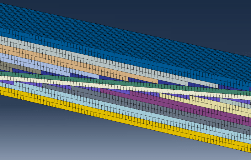
I am trying to model a scarf joint using cohesive elements for the adhesive. The adhesive mesh is modelled using a mixture of wedge and hex elements to create a "structured" mesh.
Taking a look at the adhesive part, the way that this is accomplished is by assigning a structured mesh to the middle parts, and a hex-dominated sweep to the triangular parts.
(Do not mind the fact that there are two elements through the thickness of the adhesive, this is something I can control with a script.)


Problem?!

However, when taking a look at the mesh stack orientation of the adhesive (cohesive) elements, there seems to be some inconsistencies at the areas between hex and wedge elements, since the mesh stack is assigned using faces.
I want the mesh stack orientation to follow the Y-coordinate of the CSYS I have create denoted CSYS Bondline, which is depicted in the two first figures.
Is this possible or are there any workarounds?
One possible solution I have found is to remove the triangular parts of the adhesive completely - like the article "Application of a Direct/cohesive Zone method for the evaluation of scarf Adhesive joints (2018)".

I am trying to model a scarf joint using cohesive elements for the adhesive. The adhesive mesh is modelled using a mixture of wedge and hex elements to create a "structured" mesh.
Taking a look at the adhesive part, the way that this is accomplished is by assigning a structured mesh to the middle parts, and a hex-dominated sweep to the triangular parts.
(Do not mind the fact that there are two elements through the thickness of the adhesive, this is something I can control with a script.)


Problem?!

However, when taking a look at the mesh stack orientation of the adhesive (cohesive) elements, there seems to be some inconsistencies at the areas between hex and wedge elements, since the mesh stack is assigned using faces.
I want the mesh stack orientation to follow the Y-coordinate of the CSYS I have create denoted CSYS Bondline, which is depicted in the two first figures.
Is this possible or are there any workarounds?
One possible solution I have found is to remove the triangular parts of the adhesive completely - like the article "Application of a Direct/cohesive Zone method for the evaluation of scarf Adhesive joints (2018)".


