Eng-Tips is the largest engineering community on the Internet

Intelligent Work Forums for Engineering Professionals

  • Congratulations waross on being selected by the Tek-Tips community for having the most helpful posts in the forums last week. Way to Go!

Miami Pedestrian Bridge, Part VII 51

Status
Not open for further replies.

JAE

Structural
Jun 27, 2000
15,432
0
36
US
A continuation of our discussion of this failure. Best to read the other threads first.

Part I
thread815-436595
Part II
thread815-436699
Part III
thread815-436802
Part IV
thread815-436924
Part V
thread815-437029
Part VI
thread815-438451


Check out Eng-Tips Forum's Policies here:
faq731-376
 
Replies continue below

Recommended for you

SFCharlie said:
I am amazed at how many of the long standing members nailed it back in Part 1.

Ya... two months ago, thereabouts... Some of the long standing members have decades of experience. not at all surprising.

Dik
 
I think now though with new testimony it is clear that the rods in no 11 were being tightened to "pull up" the column and close the crack(s) at its base.

I still don't have a clear view whether the top or bottom of no 11 failed first but my probable cause is the bottom.

The design does appear to be at best "non srandard" and at worse poorly analysed.

Remember - More details = better answers
Also: If you get a response it's polite to respond to it.
 
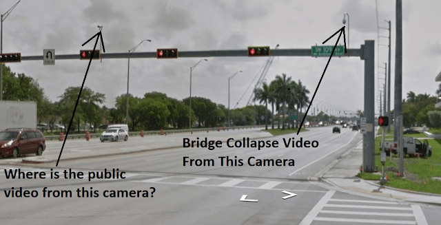
Hopefully when the NTSB releases their preliminary report, they will also release the actual Traffic Cam footage. I don't accept that they failed to record and make a copy of the Traffic Cam footage. Indeed, if they in fact failed to record the incident, then that itself requires an investigation. Shortly after the accident, they shut down the public feed of the traffic cam and have since, removed the cam from the public website menu.

bridge_collapse_camera_video_aoyzen.png
 
I looked some, but couldn't find how to calculate/estimate self-weight point loads.

Some have assumed a percentage of total weight on upper/lower nodes (33%, 67%), then divided total weight to get kips/foot.
I tried by calculating volume of components, dividing total volume into total weight, then distributing it to each node with canopy, blister weight on upper nodes, and deck, truss, diaphragm on lower nodes. End result (12017 cf/950 kips) yielded 158 lbs/cf - heavy for concrete (150 lbs/cf), but there's steel in the span.

I'd appreciate if someone could give me guidance (if simple) or a link to read.


I would normally treat the top chord as a continuous beam with supports at the panel points and use the reactions obtained as the point loads.

Dik
 
epoxybot said:
Indeed, if they in fact failed to record the incident, then that itself requires an investigation. Shortly after the accident, they shut down the public feed of the traffic cam and have since, removed the cam from the public website menu.

One of my concerns about the report from the NTSB.

Dik
 
jrs87 - This is the best I can supply. When I first checked about a week after the bridge collapse, my recollection is that there were 3 traffic cams on US41 and now there are none. Perhaps they are all part of the same feed network. Maybe there is construction work that has disabled them but why the no longer appear on the traffic cam map is odd.

Link
 
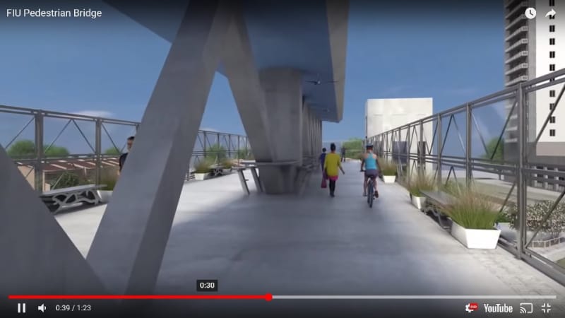
Another possible sign poor judgement was used designing bridge. Several feet of free passage width were to be used for planters, benches, and tables? If so, to use this much width for non-function use is pure folly. We all know any increase in width for a suspended load comes at a non-linear cost. I hope to run numbers to see what a practical width would be for expected foot traffic. Decided not to bother when I discovered stairway on north end was to be less than 11 feet wide and the elevator is small. So they meant it when they said this bridge was to be "floating public space". This is a world-wide growing trend, parks and gardens on rooftops for example.

We may be a victim of our own success. Failure is so rare, people stop realizing danger is there. Building this bridge was dangerous... because building ALL bridges is dangerous.

prop_n0arfp.jpg
 
epoxybot said:
If the canopy isn't stressed before #2 & #11 are stressed, wouldn't the canopy crack somewhere between the 2/3 & or 10/11 blisters?

Difficult to say. Members are short so axial deflection would be small. That said, I'd be surprised if any of the diagonals were stressed prior to the longitudinal PT.
 
epoxybot (Structural) said:
Hopefully when the NTSB releases their preliminary report, they will also release the actual Traffic Cam footage. I don't accept that they failed to record and make a copy of the Traffic Cam footage. Indeed, if they in fact failed to record the incident, then that itself requires an investigation. Shortly after the accident, they shut down the public feed of the traffic cam and have since, removed the cam from the public website menu.

bridge_collapse_camera_video_aoyzen.png

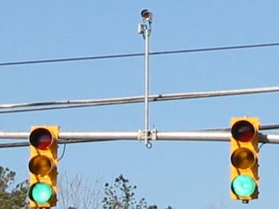
That is a video camera detector for sensing vehicles in the left turn lane. Video camera detectors are a new sensor technology in use at some traffic signals. These detector systems use digital image processing to detect a change in the image at a specific location in the travel lane due to the presence of a vehicle. Video camera technology potentially allows a wider variety of vehicles to be detected than with inductive loop sensors, but the camera must be properly installed and adjusted for this to work.

Will not have a wide vision and most likely would have not picked up the bridge collapse.

signalcam1_hkggmv.jpg


A traffic detection camera
 
bimr: thanks for confirming that (and 3DDave for the link). In CA they have (old tech) sensors under the pavement to detect traffic/regulate signals. In MO they have these cameras at newer intersections - I'd wondered if they were for red light runners [at a new intersection by my house, after a year the lights were still badly timed.. been in CA 6 months so maybe they programmed them by now].
-----------------------------------------
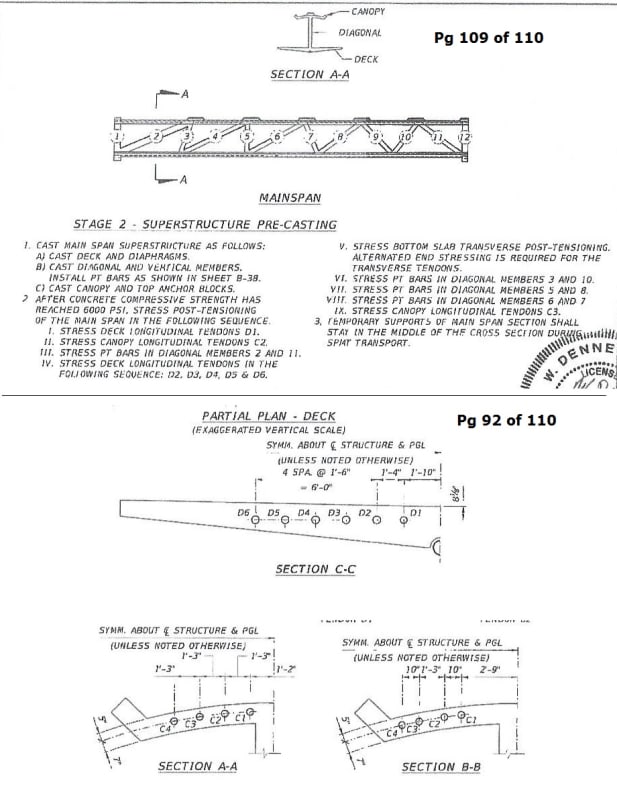
Below is tensioning sequence for mainspan.

The 2/6/18 memo said hairline cracks only in #3 and #10 showed after stressing rods in #2 (on 1/30/18) and #11 (on 1/29/18).
The 2/28/18 memo said bad cracks at base of #11 showed after the formwork was removed - which is what triggered the cracks (cracks happened before repositioning SPMTs, cantilevering span ends, moving the span, etc - which removes most of the ABC concerns of building elsewhere/moving into position). This should have raised red flags since three of four engineers who only saw the photos said it indicated eminent failure. I'd like to know how far the #11/deck crack in Photo 4 extended toward the north end.
000-stressing-canopy-deck_hvvtfl.jpg
 
jrs87 - So many things about this project's stated objectives are nonsense. I watched an interview with an FIU student after the collapse, the student mentions during the conversation that HWY 41 traffic (5 to 6 lanes) is pretty noisy. Now imagine vehicles at a stop, under a bridge and the noise, that generates. The whole idea of a "Public Space" was silly. What above exhaust fumes?

Has anyone checked with major paint manufactures to find out if TiO2 in paint & formulated for concrete behaves in the same self-cleaning manner as these TiO2 parge coats? Parge coats are labor intensive and this bridge is a good example of how variable this kind of application coverage can be.

In the original planning proposal used for directing Design/Build bidders, T.Y. Linn's bridge recommendation was for a steel & concrete truss design because truss structures were recognized as good examples of how a structural element & missile screens could come together in function & architectural presentation. The bid request specifically called for the Missile Fence to be incorporated into the structure rather than free standing. FIGG/MCM seems to have completely ignored this concept and it makes me wonder what the proposals by the other two bidders looked like. The FIU selection committee bares some responsibility for discounting T.Y. Linn's recommendations and choosing a "Never Been Done Before" design, when the entire premise of the project was Safety. Maybe the Miami-Herald should ask to see the other bidder's proposals. Granted Facchina Construction Company the final remaining bidder is now defunct.
 
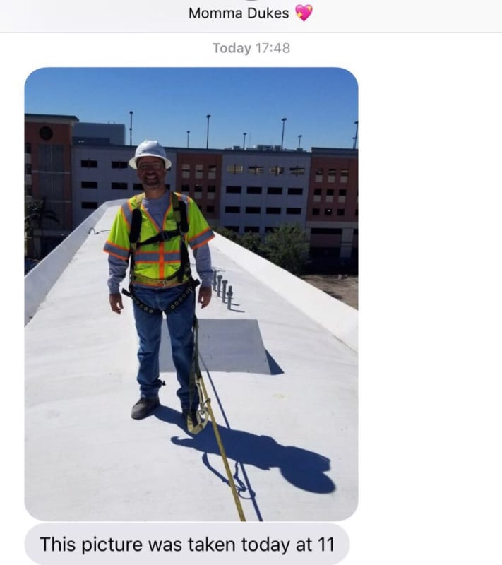
Clear (and blocked) view of blister. Is see nothing remarkable. According to Internet, this photo was taken on day of collapse and this worker was on canopy at time of collapse and survived. I have his full name, but choose not to disclose it at this time. My question is, can anyone here determine markings on hardhat? I'm curious who he worked for. It seems to me three people only does not add up if they were trying to mitigate cracking. Who was monitoring cracking as they changed stress?

DYYKR1oXkAAx2WX_gecjza.jpg
 
I wonder if this is the worker who latched his harness when he heard a crack - I thought he may have been hidden behind the crane with harness suspended from it. Three Structural Technologies workers were there - Mr. Brown, and two went to the hospital, but I never read any more about the third. A couple comments somewhere said no one was watching the cracks, but it'd be logical to do so if rods were tightened to close them (maybe even Denney Pate) - if the road wasn't closed, no one should have thought it hazardous to stand there.

This came out a couple days ago about the crane and explains why post-collapse photos only show the bucket lift.
 
Status
Not open for further replies.
Back
Top