Eng-Tips is the largest engineering community on the Internet

Intelligent Work Forums for Engineering Professionals

  • Congratulations waross on being selected by the Tek-Tips community for having the most helpful posts in the forums last week. Way to Go!

Miami Pedestrian Bridge, Part VII 51

Status
Not open for further replies.

JAE

Structural
Jun 27, 2000
15,432
0
36
US
A continuation of our discussion of this failure. Best to read the other threads first.

Part I
thread815-436595
Part II
thread815-436699
Part III
thread815-436802
Part IV
thread815-436924
Part V
thread815-437029
Part VI
thread815-438451


Check out Eng-Tips Forum's Policies here:
faq731-376
 
Replies continue below

Recommended for you

The prosperlaw fellow is a personal injury lawyer, otherwise known as an ambulance chaser. The other side of this is the construction defects civil lawsuit, in which I think FIU would be the plaintiff. And then there is the possibility, as dik indicated, of a criminal action.
 
In this locale, lawyers use a 'scattergun' approach... lawyers can be sued if their case fails and there is someone that was missed. Someone they should have sued, and, didn't.

I suspect FDOT will figure heavily into this. I assume they are like most government agencies who disclaim involvement... but are at the table for all morsels and scraps. Governments seem to thrive on involvement. I noticed the lawyer included them in his list of ???

They may have positioned themselves into first place.

Dik
 
I'm reminded of a Prince Rupert's Drop...

Dan - Owner
Footwell%20Animation%20Tiny.gif
 
Greetings jrs87 and SFCharlie

Regarding the Bridge Testing, in Spain , for instance, it is typical to perform a load test on a bridge after construction to everify its behaviour in service. See below some examples.

1185_1433_listado_detalle_i3xrpn.jpg


Imagen42_a1wgys.jpg


prueba-puente-28-2_ol70zu.jpg


Puente_svqj4y.jpg


As you can see, it is done with trucks full of sand. Several arrangements are perform to evaluate the critical load conditions.

In the USA, well... I have not heard of any load test similar to thos that can be sen in the pics.

for the moments in the Miami structure, Mr. Kaljas has shown somenumbers.

Best regards
 
3DDave said:
If I am reading it** right, modulus of elasticity is about 5 psi/ppm. In #11,.. 33 feet long - so about .0074 feet; 0.09 inches. In contrast the total delta on the tension members is 1.40 inches.

This relates to what GreenLama brought up about the deck not being tensioned before the members were poured. I (no structural background) never thought about concrete compressing. If relative to 0.09" over 33', the 174' deck would compress about 0.5" which would stress the rigid member connections (along with tensioning in the canopy), to pull in the bottom and open the ~36o angle of #11. It isn't much, but could this add to the problem of a weak 11/12/deck connection?
 
Mad Spaniard....they must pay those truck drivers a LOT of money to load the bridge and stand their waiting to see if it collapses or not.

Check out Eng-Tips Forum's Policies here:
faq731-376
 
chris snyder said:
...compress about 0.5"

Modulus of elasticity: AASHTO Load and Resistance Factor Design Manual Sec 5.4.2.4

Tendon stress can easily compress 175 foot span a visible amount. I don't know what PSI they pulled tendons at (6500?), and I don't know what happens as concrete continues to cure after post tensioning. It's correct to be concerned about the effect of this on truss system. It's not related to this accident, but concrete can also creep and stretch.
 
greetings again jrs87

I am 100% sure that the designer made an analysis accounting for the time dependent properties of concrete (creep, shinkage, increased strength with time) and post-tensioning (relaxation) with a computer program that accounted for the changes in structural scheme during the relevant construction phases. This is typical of such structures in the State of Florida and there are many commertialy available programs that so so (SAP2000, LUSAS, LARSA, etc...)

We can expect that the analysis would have results at the times of casting the main span, post-tensioning the main span, moving the main span, placing the main span in the supports, casting the back span, stressing the back span tendons, stressing the continuity capony tendons, releasing the falsework, casting the pylon and attaching the stays, end of construction and 10,000 days after the end of construction (and potentially several other intermetiate time and construction phases).

The computer program would have accounted for the fact that the PT was stressed when the strength was 6500 psi and would have given very slightly different results (but not of the magnitude that would cause failure) if it was instructed to streess when the strength would have been 8500 psi.

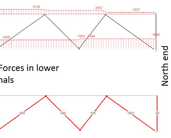
So, let's see what the designer's calculations tell us or what some brave soul out there like Mr. Kaljas has gotten for all of us.

And BTW, I am sure that they moved the span when they were sure that the concrete strength was 8500 psi. Even if the Contract drawings do not say so in the erection sheets.
 
The Mad Spaniard,

One drawing is missing within the updated work done by Mr Kaljas. There is no drawing showing the loads in ALL members resulting from stressing of the longitudinal PT. Take member 10 for example. If I'm reading his presentation correctly:
Axial-PT = 1570 K
Axial-DL = -862 K
Axial-total = 830 K

However, 1570-862 = 708 K, which is a difference of 122 K. I don't expect Mr Kaljas to redesign this bridge for us, but I was just curious. Thanks.

Dead Loads:
DL_nqw8ph.jpg


PT Diagonals:
PT-1_v0tklw.jpg


Longitudinal PT:
PT-2_nd3nqn.jpg


Dead Load + Total PT:
Total_xf2ngy.jpg

Link
 
Mad Spaniard, despite our picking apart this project, I fully agree designer accounted for all the core details we bring up. Conversely, I do feel the standard to criticize the concept (not the engineering) of this bridge is looser. And no computer program as an output that says you can skip empirical testing of a new concept. I believe the biggest contribution of this thread is providing strong evidence this design concept and building technique combined is untested and unproven worldwide. Kansas City and Columbia both occured while I was in college and made a lasting impression on me.

The rubble fracture is consistent with 8,500 PSI. Aggregate snaped. I have seen some analysis that states over reinforcement with re-bar can be just as bad as too little as it removes what little ductility there is. I don't know.

P.S. Sorry about the load test image.. did not mean to go there. I've tried to quit this thread many times, but it's too intriguing. My son is in high school and the events in Texas this morning have left me stunned, so I think I will quit now for a while.
 
Greetings TheGreenLama

The axial PT value (1570 Kips Compression) that you mention is the result of applying diagonal PT bars to the truss. . It does not include the effects of the longitudinal tendons in the canopy or the deck. The dead load effect (862 kips tension) Plus the effect of the PT bars (1570 kips) plus the effect of the longitudinal tendons in the canopy and the deck ( 122 kips compression) provides the total of 830 kips compression.

So what happens is that even if you prestress the heck out off the deck or the canopy , the relative stiffness between the longitudinal members (deck and canopy) and the diagonals causes the diagonals to get very small axial forces out of it.

Best regards
 
Greetings jrs87

What has been happening lately in our high schools is very sad. I never had to worry about it very much here in the South when my daughter was there 12 years ago. I understand your distress.

But keep in touch with this thread. At the end, when we learn the reasons for this failure , I am sure that our faith in math and physics (and code requirements) will be rewarded.

Be well.

Live long and prosper.
 
The Mad Spaniard,

I don't want to belabor the point about what is likely a rough computer model, but what you're saying about the change in axial load (122 k) from the application of the longitudinal PT amounts to a 15% change in loading in member 10. I don't consider that insignificant. Are there moments generated as well within the system from the PT loads? For me that would be a disastrous by-product, due to the minimal shear reinforcement provided in the diagonals.

Thanks
 
Status
Not open for further replies.
Back
Top