Eng-Tips is the largest engineering community on the Internet

Intelligent Work Forums for Engineering Professionals

  • Congratulations waross on being selected by the Tek-Tips community for having the most helpful posts in the forums last week. Way to Go!

Miami Pedestrian Bridge, Part VII 51

Status
Not open for further replies.

JAE

Structural
Jun 27, 2000
15,432
0
36
US
A continuation of our discussion of this failure. Best to read the other threads first.

Part I
thread815-436595
Part II
thread815-436699
Part III
thread815-436802
Part IV
thread815-436924
Part V
thread815-437029
Part VI
thread815-438451


Check out Eng-Tips Forum's Policies here:
faq731-376
 
Replies continue below

Recommended for you

For PT strand anchorages, the manufacturer provides spiral reinforcement directly behind the anchorage. It is still the responsibility of the engineer to check the zone situated further behind the spiral. For threaded bar systems no such spiral is provided by the manufacturer, so it is solely up to the engineer to detail this region.
anchorage-2_i9srlg.jpg

anchorage_fhjzuj.jpg
 
Those picture represent confinement for the axially applied post-tensioning only. Similar to column ties, which confine the longitudinal bars when they are in compression.

In the Florida bridge truss/frame, there was also a lot of flexure and shear in the joints, and I think that was not accounted for.
 
That was my next question- so the confinement reinforcement for certain types of PT tendons is defined by the manufacturer of those tendons.

In cases where the confinement reinforcement is (for lack of a better term) 'included' with the PT strand design, how common is it that additional confinement reinforcement is required?

Or, asked another way, how easy is the oversight which appears to have taken place- no additional confinement reinforcement in the 11/12 nodes?
 
The type of connection at the 11/12 and deck slab node is unique to this world, so overlooking of development, anchorage, and confinement should not have occurred, whether there was post-tensioning involved or not.
 
I wouldn't go so far as to say no confinement reinforcement is provided. As far as I can tell, drawing B-61 [ Link] shows reinforcement details at the truss joints. To me it looks identical for all joints (except for truss member 3-4 where there actually is more). This is just a feeling, but I wouldn't expect this to be the case because loads are likely different at every joint: PT, axial, shear, bending. If anyone has been able to find in the design drawings a detail for additional steel called out for PT anchorages at these joints please post.
Reinf-B61_tcvzf3.jpg
 
Understood. I apologize if my questions are causing us to go back over material that's been covered before- but for someone not at all versed in the minutiae of concrete design, this thread is like drinking from a firehose. It's terribly interesting but there's an overwhelming amount of information.

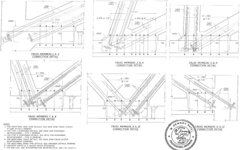
Re: reinforcement schedules shown in the post above:

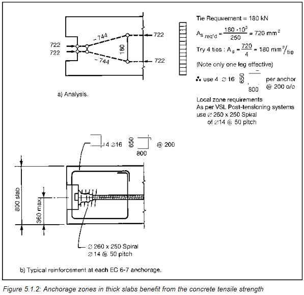
The reinforcement shown looks to me (a non-concrete reinforcement engineer) to be remarkably light, compared to the references.

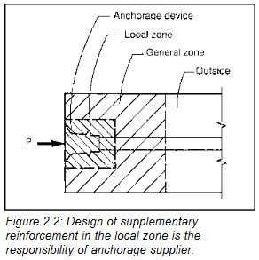
Much of it appears to be located in the 'general zone' and beyond (as described in TheGreenLama's reference graphic 2.2), especially at the critical 11/12 node.

Is localized crushing under the PT tendon fittings, where there appears to be almost no confinement reinforcement in the local zone, the potential initial failure mode the structural guys are seeing?

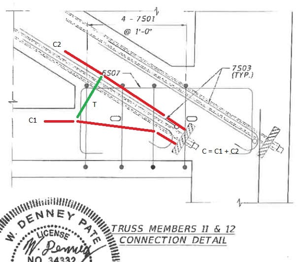
In the case of the upper tendon at #12, only the L-hooked bars appear to pass through the 'local zone' at that tendon's fitting, and based on the references I don't see how those bars provide much confinement since they develop tension (and appear to provide confinement) in only one axis.

When reinforcement schemes are analyzed, are bars loaded in bending considered to provide reinforcement, are are they disregarded?
 
Hay, I'm a computer scientist, so what do I know, but from what I saw in the drawings, the joint at 1 - 2 had 50% more rebar than 11 - 12. I wish I knew why they beefed up 1 - 2, and why they didn't beef up 11 - 12 at the same time? It's the human factor that throws me.

SF Charlie
Eng-Tips.com Forum Policies
 
jgKRI,

I'll take a crack at some of your questions.

1) Reinforcement does look remarkably light and uniform.

2) Crushing should never be an issue as plate size will have been designed by manufacturer to transfer specified design load.

3) Circular anchorages for PT strand transfer load to concrete over a different surface area than the flat plate, thus the need for spiral steel immediately around that type of anchor. In other words, flat plates generally don't require spiral steel immediately behind plates.

4) Overall geometry of concrete section plays a role in how load moves from anchorage into structure. In our case it's not simple.

5) Generally, you'd only consider steel perpendicular to strand/bars to contribute. If it crosses at an angle you might consider a fraction of it to be effective, but there's no hard rule on this.

6) In the 11/12 joint area we also have a very large compressive force from dead load. I haven't quite figured how this impacts PT anchorages. I would think a good practice would be to still address anchorage zone issues regardless of other loads.
 
SFCharlie said:
...why they didn't beef up 11 - 12 at the same time?

Member 11 was not inline with faux stay, so making it larger would disturb visual design. In another asymmetrical aspect of the design, the deck diaphragm on north end was much smaller than the one on south end.

Concrete bridge construction reference with excellent illustrations and warnings:
 
jrs87 said:
In another asymmetrical aspect of the design, the deck diaphragm on north end was much smaller than the one on south end.

The south end of the span was designed to float independently on bearings with an expansion joint.
The north end would be fixed to the pier and supported (to a degree) by the backspan after completion.

The south end was a lot stronger, but still only had a rebar cage (no chevron ties, steel reinforcement, etc), thicker truss, larger base for #1/2, thicker diaphragm, #1 wasn't hanging off the deck (like #12), and the 3D stress was much lower (per Mr. Kaljas's analysis). I don't know if #1 had two ~3" vertical PVC pipes on each side and other "protrusions" from the deck (visible in photos). It was strong enough to hold during the collapse.

There was a problem at #11/12/deck because it cracked after initial PT tension and shoring was removed. They moved the span anyway, and first mentioned cracking after the move (those 2/28 photos are rather damning..). No one would have wanted to say or hear the span needed to be redesigned "just" because of that #11/12 node (as said one engineer in the Miami Herald article after he saw the photos). I'm curious if someone sensed it was weak, but that the north end would hold until bridge construction was completed.

 
Let me just add one more thing before I'm off for vacation. Looking at the geometry of drawing B-61 more closely (detail shown here), what's to prevent a good portion of the PT force of the bottom PT bar from going into the deck slab instead of diagonal 11? (Excuse me if this has already been talked about before by someone else; maybe chris snyder.) My strut-and-tie diagram is not very good, but I think the result would be to induce a tensile force at the inside corner, potentially resulting in splitting in this area. Reinforcement would need to be detailed to prevent this. Now we don't know if they were in fact stressing or destressing this bar at the time of collapse, but as a general rule the anchor location, geometry, and existing detailing is concerning.
Reinf-B61-a_cigeeq.jpg
 
chris snyder (Electrical) said:
I don't know if #1 had two ~3" vertical PVC pipes on each side and other "protrusions" from the deck (visible in photos). It was strong enough to hold during the collapse.
Thanks for your insights. #1 has four vertical PT rods, seen at the top and bottom hinges. The hinges also had the side effect of providing access to the PT rod couplings.

SF Charlie
Eng-Tips.com Forum Policies
 
And then there's that pesky construction joint just above the anchors. We don't know exactly what it looked like because the forms for the truss were in place when the deck was poured, and we don't know how much time elapsed between the pours.
 
chris snyder said:
it was weak

Thanks Chris, your post is right on. They had to know north end was... let's say non-optimal while bridge was incomplete as they designed it that way. I'm not saying they had malaise or were negligent, it's more subtle than that. I'm not sure movers knew about any problems because I have seen video of them casually hanging out under span. Comments from residents of area are appearing that pre-collapse called bridge an accident waiting to happen and noted how ugly it was. I digress, the ugliness of bridge is off topic.

The pdf I linked to discusses temporary use of PT bars during assembly.

Keep going Chris, I think all of us are happy with the quality of your posts.
 
TheGreenLama said:
Crushing should never be an issue as plate size will have been designed by manufacturer to transfer specified design load.

With the concentrated compression loading, due to the differences in stiffness, with post-tensioning you often develop high tensile stresses. This is one of the reasons for the added reinforcing around the anchorages. It's often not for crushing.

Dik
 
I had hoped that the NTSB would release at least photos of the several bridge structural components that they are examining, that would show for example:
the end of the deck diaphragm that had been up against the pier
the end of the 10-11 blister that had been up against the canopy

I also hope that the start date of the embargo could be moved closer to the time of the collapse.

Maybe you who have questions that should and could have been addressed; would post them please.
Thank you all very much,


SF Charlie
Eng-Tips.com Forum Policies


I am puzzled that they were stressing the PT bars. Why?

Were they trying to close a weak interface plane?

If they found a problem in the design (or construction) that required fixing, why they try to fix it without closing the road until the end of construction?

What happened that morning in the meeting that resulted in doing the fix without closing the road?

This is very troublesome. More than before when I thought that they were following the Construction drawings.

If everything is based on the cracks shown in the Feb 18 memo, why they released the PT bars on March 10 to stress them again the day of the collapse? Why they moved the bridge without fixing the problem on the side of the road?

Why a bridge (non-redundant) that is not meeting code or has a problem is allowed to be above traffic from March 10 to March 15? This does not make any sense.

We need to know more. I hope the Miami Herald gets all the info up to the moment of the collapse.

Best regards
 
Status
Not open for further replies.
Back
Top