TheGreenLama said:
Now we don't know if they were in fact stressing or destressing this bar at the time of collapse, but as a general rule the anchor location, geometry, and existing detailing is concerning.
NTSB prelim said "
On March 10 per the bridge design plans, construction crew members de-tensioned the bridge diagonal members on the north and south ends of the bridge.
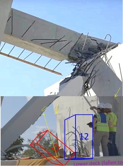
When the collapse occurred on March 15, a construction crew was positioned on the structure working on re-tensioning the number 11 diagonal member connecting the canopy and the deck at the north end of the bridge.
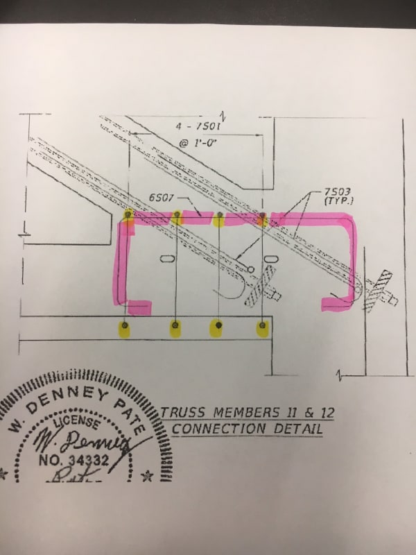
The 11/12/deck connection from B-61 (pg 86/110) above at 23 May 18 03:36, shows how re-tensioning force would transfer along the deck (adding to dead load force), now that it's confirmed lower #11 rod was being tightened. One photo shows a crack starting along the deck here. Tension on this rod was 280 kips in spec, but rod is rated at 390 kips (per Williams) - is possible they "gave it a little more" if they wanted to close the crack (Tony Pipitone's WLRN interview said ~"the work being done was to address something discussed at that morning's meeting")
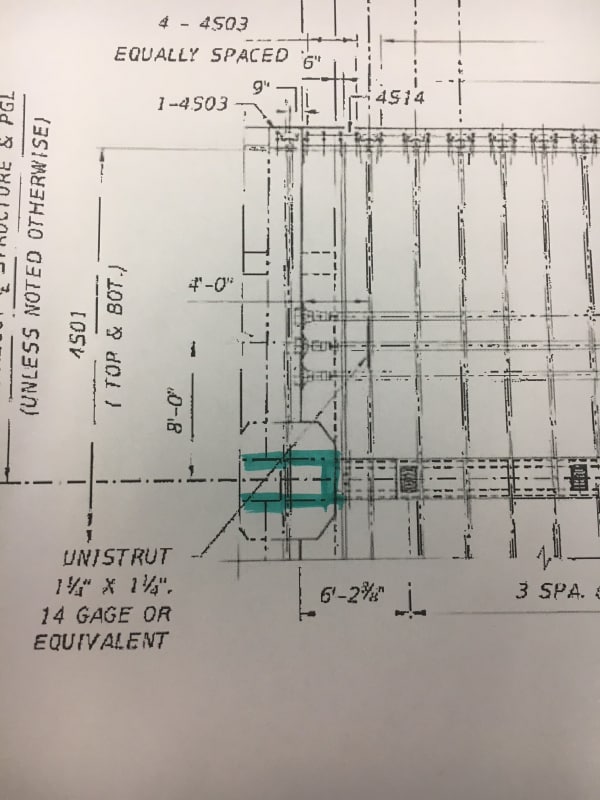
Another photo, above at 21 May 18 21:37 fm B-47,72/110, shows better with a rod that attaches deck to diaphragm.. but I don't understand how this worked.. installed after the deck was moved to something in the pier?).
[highlight these time stamps, CTRL-F will show "find", then click arrow to zip up to it.. thanks to SFCharlie for this tip.. works for Windows7 anyway..)
B-46, Pg 71/110 at lower left shows detail for two PVC pipes (labeled 4" I.D. Reinforcement sleeve, through which passes the rod to pier??). There are two on each side - NTSB photos show the deck broke at the outside edge of these PVC pipes. I didn't see such 4" pipes at any other diaphragm connections (there are two pages for each.. labeled Type I at south end of mainspan to Type IV at north end of backspan.. so Type II is at #11/12).
I was searching for deck-reinforcing rebar which epoxybot 21 May 18 18:40 brought up in that photo/angle I'd never seen before... I thought #12 sheared at the deck, but NO! the cold joint held... looks like it broke apart at the top of the (spec'd) 8"x12" anchor plate... looks like ~1.5" concrete behind it, and on 21" wide truss/support, would only have 4.5" on each side of it.
Besides higher stress at #11/12 shown in Toomas's analysis,
, 30 Apr 18 21:20
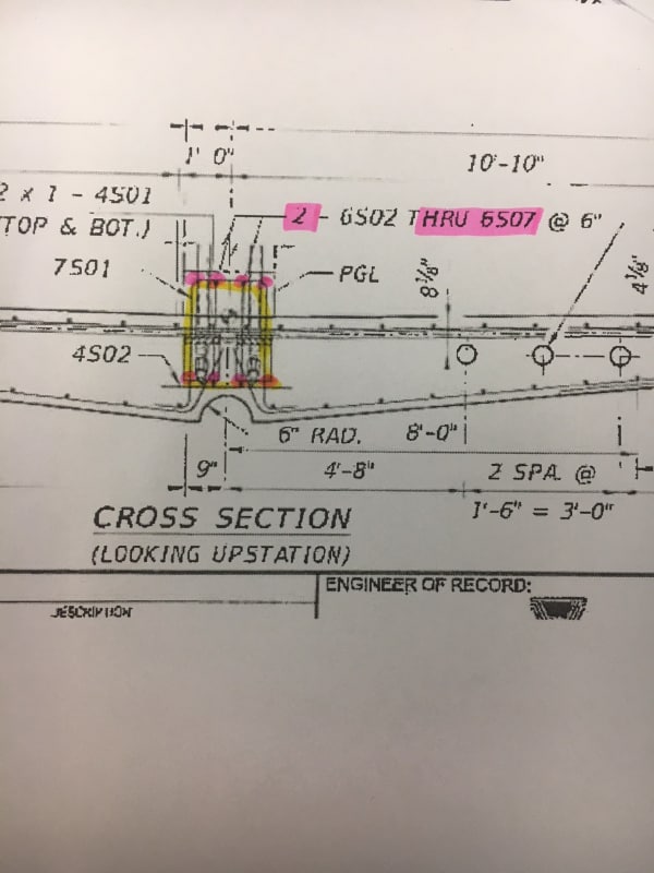
this area doesn't have much concrete supporting everything that's embedded within it (and an 8" embedded drain pipe below it).
I have some questions about my own montage above.. the duct stayed in the member about halfway down. Will look at it more later. The length matches what's on the ground.
#11 rode up #12 during collapse (can see marks), but ended up east - rebar and PT rod/duct don't look like they "mashed" against 12 as these look about same position as they'd be in the cast member (upper rod's duct is still intact).
I don't think the 1.75" rod "kinked" or bent so much, but was pushed out of the blister as deck fell, as PT rod supported #11 a bit and "eased" it east. At end of Gwideman's loop, #11 is about parallel/resting on deck, and deck is still resting on the pier. Longer slow motion video shows the deck falls after the 10/11/canopy comes down on it - jams against pier, then falls to ground.
")