Continue to Site

Eng-Tips is the largest engineering community on the Internet

Intelligent Work Forums for Engineering Professionals

  • Congratulations KootK on being selected by the Eng-Tips community for having the most helpful posts in the forums last week. Way to Go!

Miami Pedestrian Bridge, Part VII 51

Status
Not open for further replies.

JAE

Structural
Jun 27, 2000
15,444
A continuation of our discussion of this failure. Best to read the other threads first.

Part I
thread815-436595
Part II
thread815-436699
Part III
thread815-436802
Part IV
thread815-436924
Part V
thread815-437029
Part VI
thread815-438451


Check out Eng-Tips Forum's Policies here:
faq731-376
 
Replies continue below

Recommended for you

Some things were learned from that test of a concrete truss/beam in lab conditions. But the Miami bridge was a very different thing, mostly because of its cross-sectional shape. What is most tragic in hindsight is that they did not load test the structure when they had it beside the road. It would have been quite simple to do.
 
hokie66 said:
did not load test the structure

I have a feeling they did not load test it because they had inside knowledge it was not optimal until other span was placed with everything tightened and grouted. Knowing this, they would be afraid of breaking it. But then again, I could be completely wrong in this theory because they did not place short span first. It seems to me the transporter is precise enough to place main next to existing sub span.

I wonder how often they checked defection?

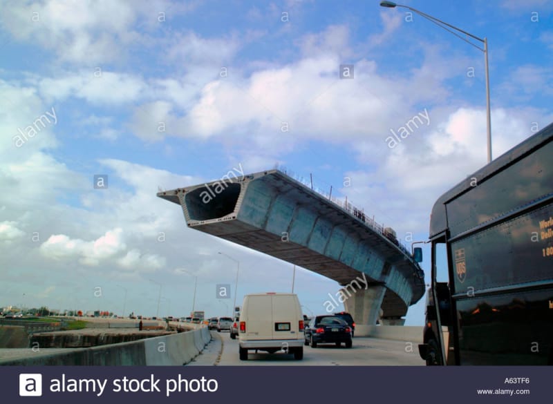
I don't know what kind of test cantilever below is subject to before allowing traffic. Partial load test? I'm not certain this photo is real.

Florida highway:

highway-bridge-construction-i95-west-palm-beach-florida-interstate-A63TF6_snwlhd.jpg
 
It is real. Precast segmental post-tensioned cantilever construction is common, and well tested now by experience. As to how much testing went into the segmental system originally, I don't know. But exactly zero load testing went into the Miami span.
 
hokie66,

Thank you for reply. I was feigning naivete and/or being rhetorical (bad habit, need to work on being more direct)... because what really bugs me about FIU bridge is how "non-academic" it was. I can find nothing that builds up to the way this project was done. No precursor designs, nothing similar in the world, no research papers, and like you said, no history of testing this concept at all.

How did this happen? Was it propriety? Have any patents been applied for?

I don't think it qualifies as a hybrid, it's a Frankenstein.

The NTSB will look silly if they do not notice this was a one-off design.

P.S.
Q. Would taking the bridge in my photo above, inverting it and adding viewports be a feasible starting point for conceptualizing a low deck span?

A. No - stick with steel through truss, it's only a pedestrian overpass paid with tax money, if it doesn't last 100 years, build another one.

My intention is not to insult the people involved, I don't think anyone could have gotten that concept to be robust. Their first submission was almost certainly sound.
 
I maybe in a minority, but, I thought the original design was attractive, and, an interesting engineering design problem. I also think the cable stayed members should have been incorporated into the design. With the 'slender I-beam/truss' configuration, the lateral torsional stability would have been a major design issue.

Dik
 
Were the pylon vertical PT rods installed through the deck? Photos of No.11 and 12 node appear to show the PVC pipes extend above the deck indicating the PT extension bar, PT back plate, and nut have not been installed.
Dwg B-46 and B-47 show four 4" ID reinforcement sleeves for 1-3/8" PT bars, two each side of No. 12.
Pylon details, Dwg B-23 appear to show only two 1-3/8" PT bars, with 4'-0" embedment
The four PT bars do not appear in the PT schedule, Dwg B-69.
Stage 3 of erection sequence, note 4, calls for pylon PT bars to be stressed, Dwg B-109
 
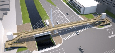
The bridge in that link looks like what they were building.

2018-05-26_1254_kpvamx.png


I thought there was an original design I hadn't seen before. I did run across this design in my earlier searching. It's certainly more attractive, and it has real cables.

2018-05-26_1304_x2bdhb.png
 
A cable stayed bridge might have closed the road for months. It might also have collapsed as the Colombia bridge did, for similar lack of appropriate design and analysis work. Just like the steel structures in the Hyatt Regency and the I-35 bridge.

Looking solely at the gross form or material choices of this bridge as an indicator of potential for failure skips investigating how the design and approval process was able to miss the flaw in this structure.

I suspect that the NTSB will find a nearly incandescent omission in the stress analysis - a clear lack of consideration for, or underestimation of, the shear retention between #11 and the deck and the aggravation of that shear by the use of post-tensioning. I suspect they will also find a lack of an independent analysis; perhaps there was a check of an originally flawed approach that confirmed the work that was done was done correctly while failing to note areas that were missed or assumptions that were incorrect, but not truly independent.

What I look forward to is an examination of the design and analysis process and some recommendations about how missing this detail could have been avoided.
 
The long span of a cable-stayed bridge could be made with six nearly identical sections built nearby. After building the support structures and the short span, the six sections of the long span could be moved into place and supported with the cables one after the other in several days. Not as dramatic as moving a one-piece span, but certainly doable. It would show off the benefits of ABC, too.
 
jrs87,

I completely agree with your post, at least everything above the P.S. This was not a matter of just tweaking some numbers incorrectly. The concept was flawed irreparably. The NTSB, as many in these threads have done, may dwell on one connection, but if so, they will be missing the forest for the trees.
 
Anyone familiar with NTSB reports would never say they dwell on one thing and miss any forest.

Edit to add: Unless the forest has been so thoroughly explored as to be familiar to everyone. Not much need to emphasize that aircraft need to have enough fuel for the entire flight and other such observations.
 
That may be the case in aircraft, but in bridge failure investigations, not so much. We will see.
 
Hokie66 - the NTSB recently released a report on a fire in a RoRo ship that was traced to the lack of a followup on a vehicle recall notice that was issued a decade before. They do more than airplanes.
 
SFCharlie said:
that you're suggesting real cables instead of pipes

It doesn't matter, either can work. It's a matter of detailing the connection.

It collapsed for other reasons.
Dik
 
We have seen the NTSB will risk life and limb in an investigation. I personally would have been very wary of being near that bent PT bar. Perhaps they checked with VSL first. Let's not forget the OIG also is conducting an investigation.

A rewatch of this video is worthwhile:
They will document emergency response and how crushed vehicles absorbed crash [crush] energy. Perhaps they will even note how the giant air lift bags were not effective here.
 
3DDave,
I know they investigate all types of transport calamities. But I am most interested in bridges, and they have investigated many, most times with assistance from outside consultants. I hope they have the right folks involved this time.
 
Status
Not open for further replies.

Part and Inventory Search

Sponsor