Continue to Site

Eng-Tips is the largest engineering community on the Internet

Intelligent Work Forums for Engineering Professionals

  • Congratulations KootK on being selected by the Eng-Tips community for having the most helpful posts in the forums last week. Way to Go!

Miami Pedestrian Bridge, Part VII 51

Status
Not open for further replies.

JAE

Structural
Jun 27, 2000
15,444
A continuation of our discussion of this failure. Best to read the other threads first.

Part I
thread815-436595
Part II
thread815-436699
Part III
thread815-436802
Part IV
thread815-436924
Part V
thread815-437029
Part VI
thread815-438451


Check out Eng-Tips Forum's Policies here:
faq731-376
 
Replies continue below

Recommended for you

A lot about analysis is being discussed here, but not much about design, which is a different part of our discipline. This was a new and flawed conceptual design, and should have been subject to rigorous experimentation and/or load testing.
 
hokie66,

As this thread is getting so long, have you ever thought about breaking it up? Say:
1) Analysis of existing as-built structure.
2) Failure mechanisms.
3) Failed design standards.
4) ?
 
TheGreenLama: too much work, and when the NTSB report comes out, there will be another flurry of information.

Dik
 
No, I see no need to break it up. I think it will proceed in spurts, as more information becomes available, or probably as more brainstorms occur.
 
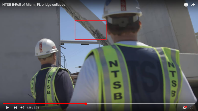
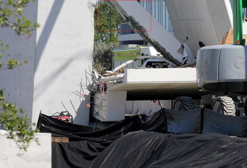
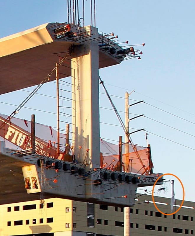
Is this duct from "upper" bar? I would not expect to see it poking out here so far away from other edge without more local damage to beam. Duct for lower bar is shown in other images still around bar going to deck.

See attachment for high resolution.

upperduct_wivdzj.jpg
 
JRS87....
That would be a west side view. That is the bottom side #11 tendon conduit, which I believe would be a short conduit section. I believe the tendon broke somewhere near there. When the canopy hit #11 at the top 2/3, it the snapped tendon, & ejected past Mr Brown. The conduit section below this area, terminates in the rubble, & as such, appears intact.
 
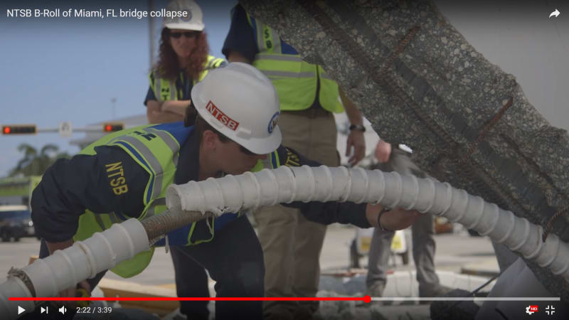
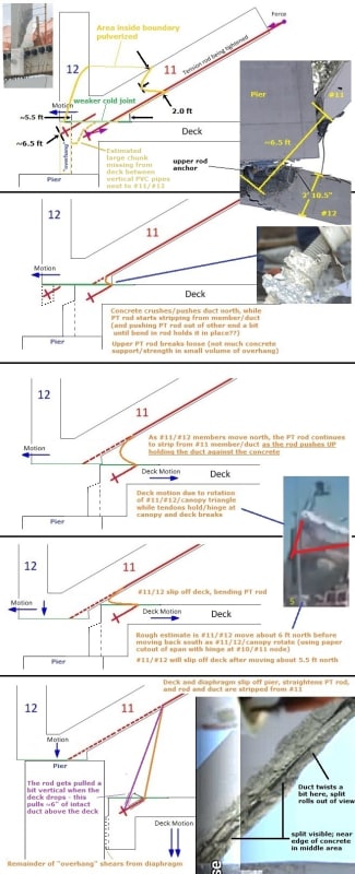
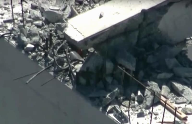
I agree it's a duct from #11's lower tendon, but suspect it's a section that remained as the rod stripped from the member - not sure what held the duct - it looks like it may be split. As some others here, I suspect the rod got pushed out as the deck fell instead of breaking. I redid the rough 'before/after' diagram using ~arc of the rod (in the bottom photo) - this makes the two rods about the same length, including the portion extending from blister.

Taking a closer look, the duct (from deck) in rubble is splayed on the north side - thinking this happened when the members sheared and the rod bent while the anchor held. The duct that's against this end (in rubble photo) has a rib which appears to be missing from the duct that's still in the member. There are two holes in the duct near the rubble... these could be caused by thread friction as ~6 ft of rod are pushed out.


 https://files.engineering.com/getfile.aspx?folder=7652322d-87a7-4751-8919-9b4297523ae6&file=02-FIU_failure_diagram-rod_ext-j.jpg
Cutterhead, Chris S., thanks. Okay, has to be lower duct. I will check how duct is manufactured to see if it is seamed.

duct_close_up_medxhf.jpg
 
Another view. A cracked edge of duct is worn through, so there is evidence duct was indeed pushed along bar towards deck. The duct still in the beam must have come from where the separation is around bar. And like Cutterhead said, the other section of duct moved in. Still, this looks odd and I see so obvious sign duct still in beam is split lengthwise. Nor do I have any idea what could have restrained it so neatly. Is there any chance this duct was for something else or is stray?

Duct_109FIUBridgedown16_NEW_PPPA_ry6axv.jpg
 
Greetings to all

I would appreciate your assistance.

I would like to see if the failure occurred at the interface between nodes 11-12 and the deck. For that, I would like to know if member #12 sheared at that interface. For that to happen (ball park) the length of the member after collapse should be about 15 feet from the bottom of the canopy to the top of the deck. At the back of the member the length should be 17.25 ft to account for the danopy end diaphragm.

At the back of menber 12, the distance from the top of the canopy end diaphragm to the bottom of the deck diaphragm is about (18+ 1.25 + 2 = 21.25 ft).

So if anybody can meassure the length of what remains of #12 using the pictures available, we can know where if failed at the bottom (ball park): at the deck interface (15 feet at the front, 17.25 ft at the back) or below the deck (17 feet at the front and 19.25 at the back) or at the bottom of the deck diaphragm (19 feet at the front and 21.25 ft at the back).

This info may have been noted before by one of you guys. It is just that I have not seen it.


Thanks in advance
 
After considering gwideman's animated loop
timestamp 28 Mar 18 07:00
and the stuck duct section, I drew out what might have happened.
There would be two causes for stripping the lower PT rod - when #11/#12 members sheer from/move off the deck, and when the deck drops.
Notes are on the drawing. I couldn't add rotation.
Bugged me that the triangle moving north in loop was dark, but it's likely in a shadow (see shadow direction of cars) - last frame shows lightening (moving out of shadow, pixelating, ???).
I estimated bottom of #11/12 would move north about 6' before moving back south - only about 2' is visible (hidden by ~2' of boom on bucket lift - right edge of boom ~lines up with north side of #12).
12_failure-move-2-j_snaobp.jpg

 
Chris Snyder,

Thank you for your postulation. Yes, this section of duct was indeed cut open by sliding bar threads, I see it now. Hope for this analysis to continue. Rotating images so member 11 is in it's precollapse position is a good idea.
 
chris snyder,

I'm not advocating one PRIMARY potential failure mechanism over another, but one thing to keep in mind, both in your photo montage as well as gwideman's photo loop, and that is that the total length of member 11 can NOT increase. As I see it, the only way for the base of member 12 to become visible is for member 11 to push it there. But the only way for member 11 to push it there, and maintain the same length, is for the base of member 11 to have, at least loosely, separated from member 12 and begin sliding up member 12. I think it's just geometry.
 
The Mad Spaniard - The back side of #12 is full length from canopy to deck. I tried last week to measure this and was not satisfied with the figures I was getting. As you can see on photos, there is only one cold joint on the back of #12. Upon collapse, #12 separates from the diaphragm just above the two rebar extending from #12 at the deck reinforcing plane.

UFO_2a_xm22eq.jpg


Ufo1_rwstmx.jpg
 
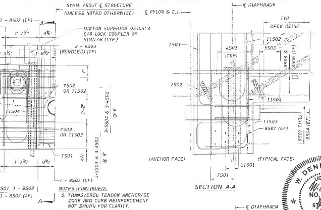
For anyone interested, something from the vault: VSL Report, "Detailing for Post-Tensioning." [Link]

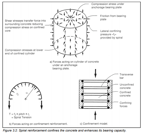
Too bad they don't discuss our 11-12 joint area. There's a lot of discussion about the tensile forces that develop behind, and between, anchorages using strut and tie diagrams. All this talk of possibly stressing PT in member 11 to close cracks made me think about whether adequate confinement reinforcement was detailed in the already critical zone where 11 intersects deck.

Just one more thing to consider.
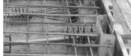
Reinf-4_mogje1.jpg
 
For the non-structural engineers in this thread who are trying to follow along...

Can one of the structural gurus kindly define the term "confinement reinforcement"

I'm only about 70% sure that my understanding of that term is accurate.
 
The picture on page 2 and the diagram on page 8 of the reference TGL posted above might help.

2018-05-22_1011__spirals_knxspb.png


2018-05-22_1005_confinement_ntytru.png
 
Status
Not open for further replies.

Part and Inventory Search

Sponsor