Continue to Site

Eng-Tips is the largest engineering community on the Internet

Intelligent Work Forums for Engineering Professionals

  • Congratulations KootK on being selected by the Eng-Tips community for having the most helpful posts in the forums last week. Way to Go!

Miami Pedestrian Bridge, Part XIII 81

Status
Not open for further replies.

JAE

Structural
Jun 27, 2000
15,444
A continuation of our discussion of this failure. Best to read the other threads first to avoid rehashing things already discussed.

Part I
thread815-436595

Part II
thread815-436699

Part III
thread815-436802

Part IV
thread815-436924

Part V
thread815-437029

Part VI
thread815-438451

Part VII
thread815-438966

Part VIII
thread815-440072

Part IX
thread815-451175

Part X
thread815-454618

Part XI
thread815-454998

Part XII
thread815-455746


Check out Eng-Tips Forum's Policies here:
faq731-376
 
Replies continue below

Recommended for you

Note to all:

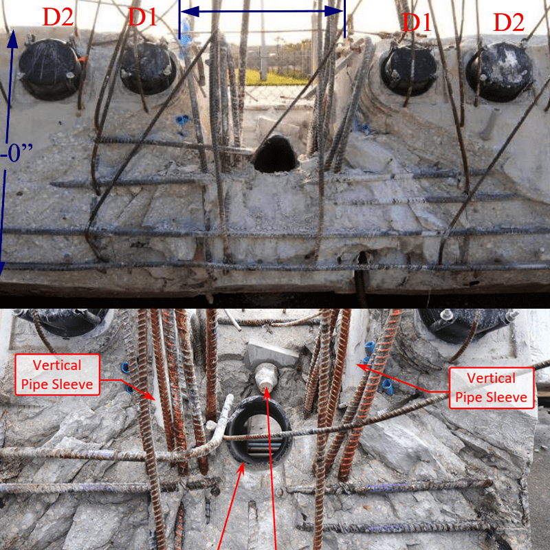
The pics show cracks in vertical column 12 which means that there is bending there. Also the #11 must have benting moment on top of comprssion forces.

The reports do not incorporate these elements into their review (not FIGG, MCM, or NTSB). These secondary or "terciary" forces may be part of the straw that "broke the camel's back"

Also, the "restressing procedure" going back and forth from the north bar to the south bar in increments may also be part of the picture in a system that is in the process of colapsing. Think about how you can break a steel wire.

Live long and prosper
 
PA PE (Civil/Environmental) said:
It would be virtually impossible to effectively roughen the surface due to the congestion in that area.
True. So if it is not possible within reason, those constructing it should ask for a change to detailing.
One question - if they can't build it, why did they bid it? Not to be harsh here but these are things to be addressed during bidding. Not when penalty days are ahead.
Supposedly there were reviews addressing constructability before approvals were granted.
A closer look while still in design could have traded more steel for less roughening.

And for similar conditions - does anyone remember the cast grid plates with spikes which were used in wood pile construction to connect beams to round wood piers? Could something like that be designed - with bearing plates above and below the shear plane and and holes to pass concrete and torch outs for the rebar and conduits to pass?
Any entreprenuers here? It would be a specialty market - there is not going to be many of these built.
 
HP said:
I'm not so sure of that. I think that if Figg had gotten their collective heads out of their butts and actually looked closely at what the cracks were telling them, they might still have snatched victory from the jaws of defeat.

They were busily designing metal straps to "capture the node" so I suspect they knew.
 
I may have been fooled - the old bait and switch trick. To be clear, the quote is from the WJE report which was requested by FIGG and presented in defense of FIGG.
So what coefficient of friction should be used with a joint prepared as FDOT requires? What coeff would you recommend for one prepared as WJE did?
The WJE tests indicate full/maximum resistance of a shear friction joint is reached at a slip of 0.020 inches. I note FDOT does not specify an amplitude - perhaps because they also think small amplitudes are sufficient. WJE 5.3.4 In the case of the interface shear tests, peak shear-friction resistance occurs at a deformation of approximately 0.02 inches. Deformations at breakout failure are about twice this amount, 0.04 inches.
So FDOT does not specify an amplitude - and apparently Florida Contractors and Engineers know that the 1/4 inch amplitude is not required. I am not sure that excuses the contractor from following FDOT requirements, particularly after the issue arose and directions were given to do so.
If the preparation by chisel by WJE improves the joint and a higher coefficient of friction can be assigned, the industry has learned something. There may be places the increase can be helpful and worth the effort.
We can add the joint preparation by WJE to the list of things FIGG will have to explain to the jury.
Thank you.
 
Hi, Charlie. As I recall, MCM bid out the forming, concrete, reinforcing, and PT to sub-contractors. It is those contractors who were the focus of my statement.
Thank you.
 
Surely a major lesson to be learned here is that friction is not reliable. Another is that if you build a post-tensioned concrete truss/frame, the design should be based on research specific to that form of structure.
 
Vance Wiley (Structural)16 Oct 19 00:46

To answer your questions:

1 If the connection is designed assuming that with "No intentional roughening" based on AASHTO LRFD (no 1/4" roughening) is enough to transfer the shear friction, then the FDOT spec based cleaning is good enough. If you notice, the value of the coefficient related to the steel capacity is 0.6. This is for practical purposes the coefficient associated with the shear (just typical shear) of a steel section : the steel bars are acting like dowels.

We have to remmember that the equations (with 0.6 coef) are based on tests performed on ( I guess) smooth surfaces. To verify that we may hace to go to the original research. The other case (1/4' roughening) equations (1.0 coeff) for the steel rebar component was based (probably) on tests that involved this level of roughening. If that level is not requested clearly in the plans you would not know if the capacity will be obtained in the field.

Anything in between, you have no clue of the capacity that will be obtained. But we have discover (thanks to FIGG tests) that even something less than 1/4" rougghening could provide you a good capacity. They were just lucky to get those results with what they did. But we can not rely on that for other designs until more tests are done to satisfy AASHTO or ACI bosses.

So, to accommodate typical construction practices, the FDOT specs must say something about cleaning the joint and make sure that no loose matter is there. The way it can be read at this moment , any contractor can use sand paper to "roughen" and clean the joint and still meet the FDOT spec. (and they will !!! and there is nothing FDOT can do about it) If the FDOT wanted to roughen the joint the way FIGG and WJE call "FDOT roughening way", they would explicitly mention the procedure and the result in a very detailed way with measurement of the roughness in the spec. So, to make contractors life easy (and FDOT too) , the spect just make sure that the joint is clean. But for that reason, engineers must design for only "dowel action".

It is not difficult to see a 1/4" roughness in the field. But anything less would require the sophisticated methods that were used in the FIGG test to quantify roughness. And that makes stuctures more expensive and can create arguments in the field if the parties do not agree on the numbers obtained. We are not building "Swiss watches" here.


Note to all: SHEAR FRICTION HAS BEEN USED IN MANY STRUCTURES FOR MANY YEARS. IT IS RELIABLE. BUT YOU HAVE TO KNOW WHAT YOU ARE DOING AND MAKE SURE THAT THE REQUIRED "1/4" LEVEL IS CLEARLY NOTED IN THE PLANS IF THE DESIGNER HAS USED THE 1.0 COEFF IN THE CALCS TO REDUCE THE VOLUME OF REBAR IN THE JOINT. REMEMBER THAT THE PEOPLE IN THE FIELD DO NOT SEE THE CALCS.


Some months ago, when I obtained the calcs from FIU and saw the analysis of the joints and the fact that no note about 1/4" was in the plans, I deducted what was the potential suspect : 0.6 vs. 1.0

Best regards


Thank you for the explanation.
In reading the PARTY SUBMISSION by FIGG to the NTSB, section 6.2.1
The design of the member 11/12 nodal connection was based on AASHTO LRFD
design specifications for shear friction (Section 5.8.4). The calculations used a
friction coefficient of 1.0 which is specified in the design code for “normal weight
concrete placed against a clean concrete surface, free of laitance, with surface
intentionally roughened to an amplitude of 0.25 in.”


It seems FIGG is admitting a special requirement for construction joints beyond the requirements of the FDOT description but did not indicate that special requirement on their plans. And further, FIGG instructed the job to follow FDOT.
FIGG is a firm with a large Florida presence - they did not know the difference between FDOT and AASHTO on this issue?

The next paragraph says this:
Since the bridge was constructed using the RFC plans, the nodal applied loads
and capacities are actually represented by the RFC plan details as opposed to the
design calculations. Section 7.3 of this report provides an analysis of the design for
the member 11/12 nodal connection as shown in the RFC plans.

Uhhh - lets see. Since the thing was constructed from the RFC plans, the loads and resistances are there and NOT in the calcs ?? Did they do the calcs, draw the plans, and ne'er the twain did meet?
It seems the WJE tests followed the intent of the calcs, not the drawings.
But why would FIGG direct or confirm joint preparation to FDOT requirements? Then the contractor did nothing - left it "as poured", because it was too much trouble, according to the testimony of a workman.
And no one at the job noticed the difference.
Another of those converging mistakes. Two, actually. No - this counts for 3.
 
The Mad Spaniard,

No matter how red you make your comments, friction is not reliable in resisting forces of this magnitude. Shear friction theory is relatively new, and not universally accepted. Where I have practiced in Australia, it is not mentioned in our code, as it is considered to be not well supported by long term practice.
 
hokie66

I am curious as to how you handle shear in a cold joint? I have used shear friction method several times (always with 0.6) and find it in my concrete references back to early 1990s (oldest codes I have which are from my undergrad days).
 
Would I not be correct to define shear friction as the ability for 2 separate parts to resist movement between? For load calculation purposes this should be a single monolithic casting of concrete. Once it became two then it has for all intents and purposes failed.

Brad Waybright

It's all okay as long as it's okay.
 
Hokie66,

Would the fact that Australia and NZ do not incorporate shear friction be because that region is more seismically active than say Florida?
 
That is basically the case in plain or un-reinforced concrete.
The problem is concrete cracks - for many reasons and almost universally. So we cannot afford to replace every concrete structure because it cracked, and reinforcing is added. And as a double benefit, reinforcing adds strength or load capacity. Plain concrete is relatively weak in tension and sometimes cracks for no apparent reason so as a structure it is not reliable. Reinforcing provides that reliability. As a gravity dam, plain concrete works quite well.
Mild or plain deformed reinforcing can resist the tension forces from loads that are supported, maintain contact across a crack and therefore maintain some shear capacity - and gives engineers jobs. Prestressing is active reinforcing and compresses the concrete, thereby closing the cracks or preventing them from developing. This structure has (had) both.
Most structures are too big and too complicated to be cast monolithically and "cold joints" are required. Incorporating those joints and getting them to perform as if the concrete were monolithic is the purpose of reinforcing and, in this case, the primary critical force acted in shear.
The proper application and manipulation of concrete and reinforcing provides jobs for engineers. Improper applications can result in structural failures and termination of those jobs.
You are totally correct - plain concrete will never be stronger than when monolithically placed and cured and uncracked. Properly reinforced concrete will be much stronger, can be engineered to serve different conditions, and can still serve well after it cracks.
 
What is being discussed here, is why we need to see the "RFI" communications. To see if MCM, Structural Technologies (Steel, Forming & Placing), FIGG & BP, (just who) and were they even discussing or to what extent, the constructability difficulties at the 11/12 Node.
 

FIGG represents the emails during construction as this:

E-MAILS REGARDING CONSTRUCTION JOINT REQUIREMENTS
The construction specification requirements for roughening construction joints
were confirmed and emphasized in an e-mail exchange between MCM (the contractor), BPA (the independent construction quality inspector) and FIGG
(designer) starting on June 10, 2017 and continuing through June 13, 2017.
June 10 at 9:20 a.m. – MCM’s Superintendent to BPA:
“We are scheduled to pour the first bottom 3.5 ft. of the South column on
Foundation Type 3 this coming Monday morning – June 12, 2017 at 8:00 a.m.
… should you have any questions or concerns feel free to contact me.”
June 10 at 10:44 a.m. – BPA’s Project Administrator to MCM’s Superintendent and
others at BPA and MCM:
“Every cold joint generated on structural elements will require a treatment with
a APL [Approved Products List] list product. Please ask FIGG their opinion and
suggestion.”
June 10 at 10:48 a.m. – MCM’s Superintendent to BPA’s Project Administrator and
others at BPA and MCM:
“The question will be asked.”
June 12 at 9:18 a.m. - BPA’s Project Administrator to MCM’s Superintendent and
others at BPA and MCM:
“…any response from Figg regarding potential cold joints? Please advise.”
June 12 at 10:06 a.m. – MCM’s Project Engineer to BPA’s Project Administrator and
others at BPA and MCM:
“Please clarify if you are referring to construction joints or cold joints. For
construction joints we will roughen the surface of the hardened concrete and
remove loose particles prior to placing new concrete.”
June 12 at 10:10 a.m. - BPA’s Project Administrator to MCM’s Project Engineer and
others at BPA and MCM:
“Yes, I am referring to construction cold joints on structural elements, please
get an answer from FIGG of the appropriate treatment.”
June 12 at 10:15 a.m. – MCM’s Project Engineer to BPA’s Project Administrator,
FIGG’s Project Manager and others at BPA and MCM:
“I spoke with FIGG and they advised us to follow FDOT specs which is as
follows:
6-15
400-9.3 Preparations of Surfaces: Before depositing new concrete on
or against concrete which has hardened, re-tighten the forms, roughen the
surface of the hardened concrete in a manner that will not leave loosened
particles, aggregate, or damaged concrete at the surface. Thoroughly clean
the surface of foreign matter and laitance, and saturate it with water.
The plan notes do not mention the use of a bonding agent so it is not required.”
June 12 at 10:37 a.m. - BPA’s Senior Project Engineer to MCM’s Project Engineer,
FIGG’s Project Manager and others at BPA and MCM:
“Lets make sure we keep FIGG informed about the location of the all future
construction joints and represent them accurately in the final as-built.”
The e-mail included an image from the bridge plans showing the south landing
bent (also referred to as the south abutment) with an arrow pointing to a
construction joint at the top of one of the columns.
June 13 at 7:48 a.m. - BPA’s Project Administrator to FIGG’s Project Manager and
MCM’s Project manager with copy to BPA’s Senior Project Engineer:
“Please make sure we have FIGG blessing for the construction cold joints
treatment, my personal experience is that a bonding agent will be a reliable
way to good because proposed method is not easy to do (column with steel)
and achieve good results.
400-9.3 Preparations of Surfaces: Before depositing new concrete on or
against concrete which has hardened, re-tighten the forms. Roughen the
surface of the hardened concrete in a manner that will not leave loosened
particles, aggregate, or damaged concrete at the surface. Thoroughly clean
the surface of foreign matter and laitance, and saturate it with water.”
June 13 at 7:56 a.m. – FIGG’s Project Manager to BPA’s Project Administrator and
MCM’s Project Manager with copies to BPA’s Sr. Project Engineer and others at
FIGG:
“We have had previous communications with MCM regarding this topic and
the FDOT specification referenced below was to be followed. Let us know if
you have any further questions.”
June 13 at 8:04 a.m. - BPA’s Project Administrator to FIGG’s Project Manager:
“Thank you.”
6-16
The NTSB Factual Report in Section 20 incorrectly
states that the above e-mail chain was strictly
limited to a discussion of construction joints at the
columns on the south abutment (south landing
bent). A review of the e-mail text shows that this
is clearly not the case and that the discussion
was regarding the treatment of all concrete
construction joints. MCM’s June 12 e-mail at 10:15
a.m. transmitting FIGG’s instructions to follow FDOT
Specification 400-9.3 was prior to BPA’s e-mail
at 10:37 a.m. that included a sketch of the south
landing bent and did not mention the south landing
bent in the text.
 
[cough] !!! [sup]TORSION[/sup] !!! [/cough]

An ominous foreboding from VVIETCIVIL.

module-1-behaviour-of-rc-beams-in-shear-and-torsion-51-638_ntwfyf.jpg


This relates directly to the structural collapse as follows:


Misaligned_Rebar_imcf4i.png

Torsion_wkgv4x.png


As it turns out, the structure is primed for torque induced stress between 11/12 and deck/diaphragm:


Torsion_rebar_interface_rqofda.gif


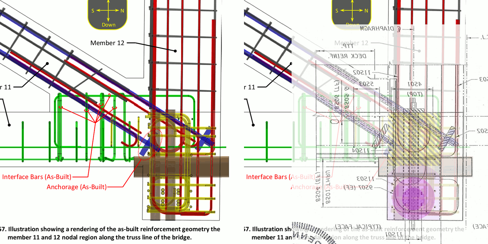
With regards to the weak surfaces forming the pocket, also note the blue conduit (previous image) that occupy significant surface area on both sides of 12. Also the shear plane skips laterally from the white tubes to the coil rebar around the PT duct. In short, an abundance of inclusions have created a nightmare scenario.


Deck_11_Overlays.2..13_dhgrfc.png


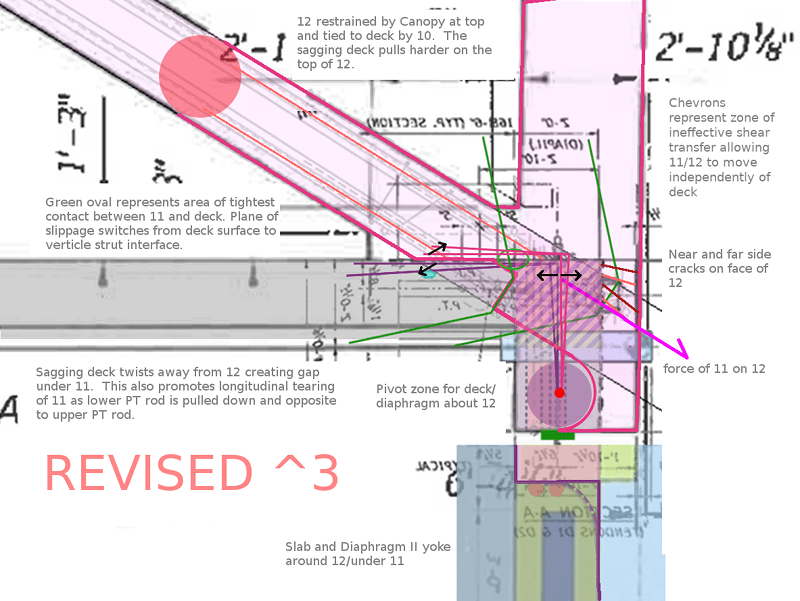
The rotational forces also put to rest any idea of shear friction as that would require a reliable base which is not provided by way of the slab or by way of 11 as they are both inclined to move opposite and apart from each other. Even a breath of movement eliminates this as a structural design element.

The #6 and #7 rebar ties between diagonal 11 and the slab provide drag and distract from the true nature of the design shortcoming. Unfortunately all of the forces carried by 11 are funneled into 12, and I don't believe that was intended.


Edit: my previous posts (amoungst others) on this page, 23 Sep 19 00:09, and on page XII, 25 Jul 19 02:18, provide more development on this theory, including the lower PT rod as a control mechanism.
 
Vance Wiley (Structural) - Email exchange. Thanks for that, I missed it somehow but why isn't Structural Technologies included? What was the distribution list? A more standardized RFI procedure would have notified all parties working on the project.
 
Sym P. le (Mechanical) said:
As it turns out, the structure is primed for torque induced stress between 11/12 and deck/diaphragm:
I think you are forwarding a post from somewhere else.
The comparison of the end of the structure with diagonal cracking was addressed by the EOR as caused by vertical load. He provided calculations that substantiated that and predicted the cracking. Vertical load seems plausible, as the direction of cracking is reversed on the two sides. Note the pictures below the OSHA image are same pic reversed.
The bearing pads were checked for level before the thing was lowered the last inch to ensure level bearing.
I need some help here - I do not see what would cause a lateral torsion (east-west).
 
Vance Wiley, thank you for the thank you.

The Mad Spaniard, thank you, I was hoping someone familiar to the FDOT Specifications and general interpretation would comment.

Both, thanks for the discussion on the FDOT specification topic.

To me, FDOT 440-4.3, is very arbitrary. There is no mention to the degree the joints are to be roughened, it would seem that the degree of roughness should still be defined in Construction Documents. An email telling the Contractor to roughen the joints per FDOT Specifications, in my experience would not have been very effective. My experience, Specifications are not much used after submittals. Sketches of all conditions and all plan groups; substructure, superstructure, etc., issued in a formal RFI to all parties would been much more effective. Many Contractors do still keep a working set of Construction Drawings on the job site and such sketches are taped and pasted into the working set of drawings. At least then it had a chance of being caught.

I have always preferred to spec the surface be roughened while the concrete is still plastic as opposed to mechanically roughening after it is hardened. I can see why some additional treatment after might be desirable, especially for bridge structures where good adhesion is desired for environmental resistance reasons, methods exist that are much easier to execute than chiseling, if the desired roughness profile already exists.
 
Status
Not open for further replies.

Part and Inventory Search

Sponsor