Continue to Site

Eng-Tips is the largest engineering community on the Internet

Intelligent Work Forums for Engineering Professionals

  • Congratulations KootK on being selected by the Eng-Tips community for having the most helpful posts in the forums last week. Way to Go!

Miami Pedestrian Bridge, Part XIV 78

Status
Not open for further replies.

JAE

Structural
Jun 27, 2000
15,460
A continuation of our discussion of this failure. Best to read the other threads first to avoid rehashing things already discussed.

Part I
thread815-436595

Part II
thread815-436699

Part III
thread815-436802

Part IV
thread815-436924

Part V
thread815-437029

Part VI
thread815-438451

Part VII
thread815-438966

Part VIII
thread815-440072

Part IX
thread815-451175

Part X
thread815-454618

Part XI
thread815-454998

Part XII
thread815-455746

Part XIII
thread815-457935


Replies continue below

Recommended for you

Thanks...

Rather than think climate change and the corona virus as science, think of it as the wrath of God. Feel any better?

-Dik
 
It's quite possible the base of 11 might have started the failure, but 12 still wasn't doing a particularly good job of staying attached to the deck as evidenced by the pictures of the cracks around it's base. If 12 stayed attached to the deck as the collapse started then when did 12 break free from the end of the deck and how did it stay on top of the pylon when the deck was pulled to the ground.
 
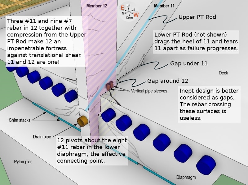
My argument is not that the base of 11 started the failure, only that it was the first note of the coda. What's worse is that two government agencies with significant engineering resources failed to identify this important detail or even identify the altered structural dynamics at play which stemmed from other structural design defects.
 
I've been struggling with the definition of 12. Does it sit atop the deck which sits atop the diaphragm or does it pass through the deck and anchor in the diaphragm? I don't really need an answer though.

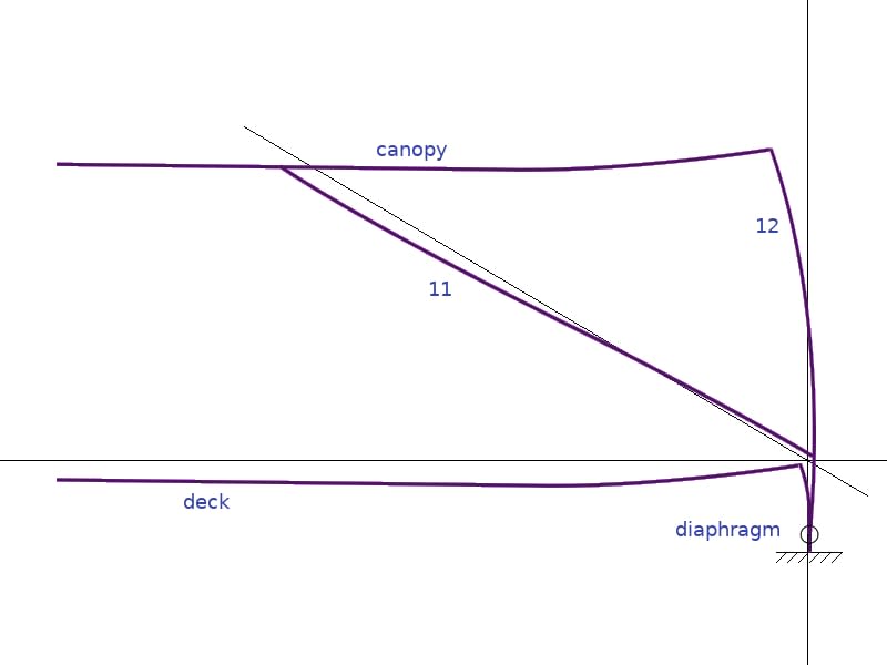
On day one, when the shoring was removed, the deck detached from 12 as per the following sketches (which are exaggerated for illustration). The situation became more obvious with time as the cracks became more pronounced. The structure managed to stay together until 11 buckled/sheared and the span started to go down. As the structure begins to go down, the top of twelve has to move north several inches to accommodate the geometry of the rotating long end of the bridge. 12 is somewhat held in its vertical orientation (though it bows considerably) while the deck rotates the diaphragm off of 12.

These sketches are not perfect but they serve to illustrate the bigger idea of what I'm trying to get across.

EDIT: The east/west arrows on the compass are backwards. It's rather karmic that I took this sketch, and compass, from the NTSB report
EDIT 2: Problem solved!

Final_Effective_Structure.01_wbdcde_s8wnyn.jpg


Bridge_Deflection_ynehlp_x5pbqr.jpg
 
Further, notice how much of 11 sits on the slab, and that portion of slab did not punch out. It is implausible that 11 could punch out the much heavier pseudo column.
 
I don't like the term "Punched out".
The 11/12 connection to the deck failed in shear.
The concrete was broken and the joint was held together by some rebar.
The lower PT was anchored at one end to member 11 and at the other end by the deck.
The lower PT rod crossed the existing failure in such a way that increased tension tended to open the existing crack.
When the lower PT rod ripped out of the bottom of member 11 and the rebar crossing the crack failed, the 11/12 connection left the deck.
The concrete had already failed days before.

Bill
--------------------
"Why not the best?"
Jimmy Carter
 
It has always bothered me from the first photos of the cold joint failure, as to where the energy (load released), eventually was transferred/relieved. Regardless of how small the movement, this failure signaled northward movement of some portion of the bridge.

I also feel that the cracks running up member 11, traveled deeper into member 11 that just delamination of the cover concrete and were a sign of eventual compression failure in 11, just in advance-of/above the 11/12 node.
I had been trying to work out, if the compression failure in member 11 & the shear failure, at the back of node 12/diaphragm occurred independently or simultaneously, as a result of de-tensioning the PT bars. And if the detetensioning of one bar created a load differential in member 11, resulting in shearing forces and cracking, inside of member 11 between the two PT bars.

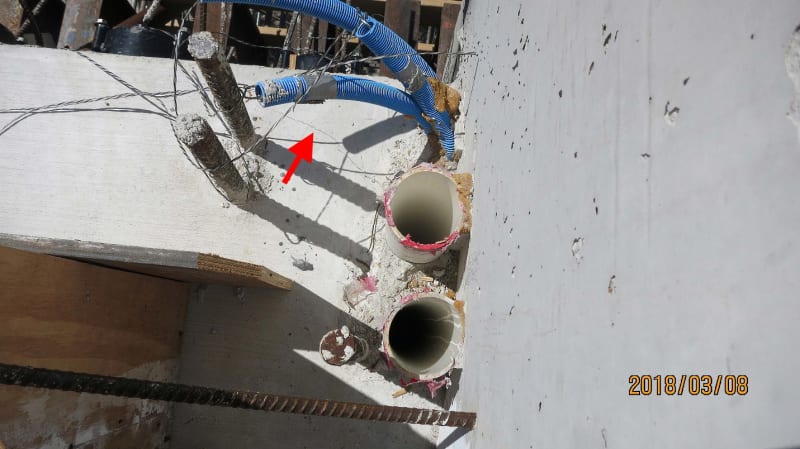
The following photo from NTSB file 628553 , page 11 (Bridge Factors Photographs - FIGG Bridge Engineers, Inc. Photo Submission) - oddly out of dating sequence, demonstrates that failure took place at the back of the diaphragm, in conjunction with the cold joint failure/shearing, while the bridge was still in the casting yard. It is where the energy was relived from the minute sliding of 11 at the cold joint.

While examination of the engineering has determined that the bridge was doomed before it was even built,
Sym P. le is correct that the failure was initiated upon removal of the shoring.

03032018_sn1p7b.jpg
 
waross (Electrical) 8 Dec 20 19:15 said:
When the lower PT rod ripped out of the bottom of member 11 ...

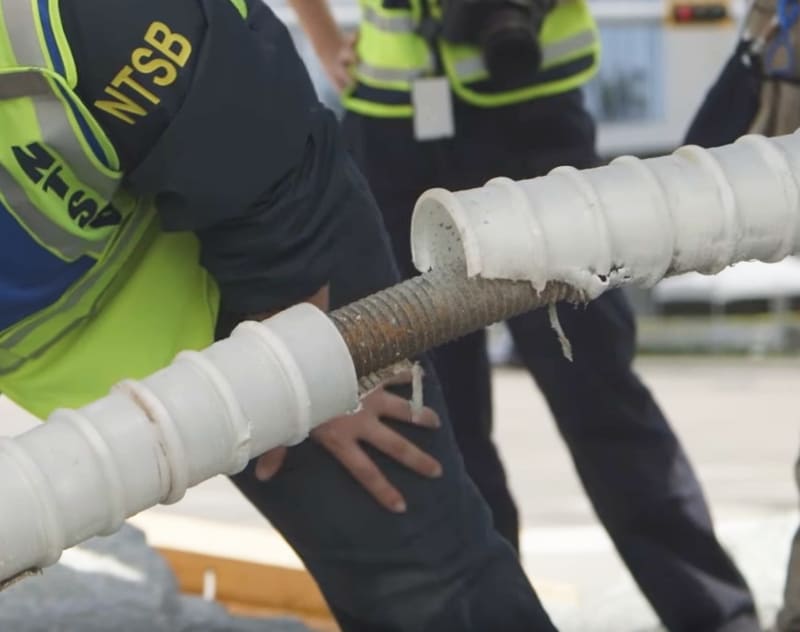
Suppose, for the sake of argument, the 1.75" lower PT rod was encased in a 3" plastic tube. At a 31 deg incidence angle, there would be 2.4" of play. In other words, the relative horizontal movement between the deck and the bottom of Member 11 would have to be at least 2.4" before binding would occur. That is not a likely scenario.

My apologies, I chased that seductive theory myself for a long time and struggled to move away from it even after I first did the calculation months ago.

NTSB_B-roll.PT_rod_fl3tmi.jpg
 
I'll take up that argument;
A 3" plastic tube will have significant buoyancy in wet concrete.
It will have been tight against the bottom of the PT rod.
The PT rod was anchored to the deck, not to the end of member 11.
It is possible and even probable that the pressure of the plastic tube against the bottom of the PT rod helped the rebar to restrain the 11/12 node when the concrete sheared and the cracks opened up.
I suggest that the failure of the rebars crossing the fracture and the failure of the bottom of member 11 when the PT rod started to rip out happened simultaneously or almost simultaneously.

I suggest that the triangle formed by members 11 and 12 and the canopy remained intact during the initial collapse.
The canopy cracked and deflected at the 10-11 node.
As the structure fell, the bottom ends of 11 and 12 were dragged across the top of the pier with much of the weight of the canopy adding to the forces.
Member 11 had already be severely compromised by the damage done when the lower PT rod ripped out.


Bill
--------------------
"Why not the best?"
Jimmy Carter
 
Now up for consideration, NEXT-GEN Column Reinforcement Technology

nEXT_gEN.02_dyw9kx.jpg
 
Remember that even though the canopy broke above the 10,11 node, it was still connected together by a number of PT rods.
The 11,12 node may well have been pulled down on the top of the pier by the weight of one end the entire canopy and the weight of most of the bridge.
That explains the damage to the 11,12 node.
Look at the pictures of the upper PT rod and the recently posted aerial photo which shows member 11 displaced sideways.
Member 11 was definitely broken at both ends.

Bill
--------------------
"Why not the best?"
Jimmy Carter
 
The only thing more laughable than the reinforcement detail at the bottom end of Member 11 is that it wasn't the weakest link in the structure.
 
Q: What's the purpose of the skewed U-shaped column tie?
A: It deflects the energy to baffle the NTSB!
 
If NEXT-GEN Column Reinforcement Technology gets incorporated into the building code, all them buildings will slide off the edge of the earth! Call your Representative now!!!
 
waross (Electrical)11 Dec 20 04:33 said:
I suggest that the triangle formed by members 11 and 12 and the canopy remained intact during the initial collapse.
The canopy cracked and deflected at the 10-11 node.
This is not consistent with what I see in a frame by frame review of the dashcam footage. Member 11 shrinks either at the 10-11 or 11-12 joint at the earliest movement.


SF Charlie
Eng-Tips.com Forum Policies
 
Sym P. Lee correctly states:

"The only thing more laughable than the reinforcement detail at the bottom end of Member 11 is that it wasn't the weakest link in the structure."

This statement is correct because member 11 was loaded in compression. Concrete has considerable strength in compression. The portion of the design that was weaker than member 11 itself was the connection of member 11 to the concrete deck.

That is because:
(a) this point of connection witnessed very high tension forces generated in the concrete deck;
(b) concrete has practically zero strength in tension; and
(c) there was no steel designed or introduced into the concrete deck to deal with this tension force;
(d) the foregoing is evidenced by the fact that the failure mode was apparent just before failure: the photographs show large tensile cracks appearing in the deck and not appearing in member 11. True, some spalling was seen on the corners of member 11 as the deck/11 node rotated, but the deck was the element that formed tensile cracks one inch wide and into which a tape measure could be inserted up to seven inches deep.
 
Would that be the dash cam footage where member 12 is hidden behind both a street light standard and a manlift boom?
Member 11 doesn't shrink, it passes behind the obstructions.

Bill
--------------------
"Why not the best?"
Jimmy Carter
 
The release of the upper PT rod after the move is what allowed member 12 to move north, thus the "cracked all to hell." An implication of this is that further travel north required further release of the upper pt rod, as such, an unlikely scenario. The upper PT rod is the key to this puzzle, not the lower one.

Member 11 displays all classic signs of compression failure both before and after the collapse. Retensioning both upper and lower PT rods caused the collapse. Edit: by overloading Member 11.
 
waross (Electrical)11 Dec 20 22:07 said:
Would that be the dash cam footage where member 12 is hidden behind both a street light standard and a manlift boom?
Member 11 doesn't shrink, it passes behind the obstructions.
No, that would be the full frame, 720, 10 fps, original dashcam footage with each frame zoomed in so that I can see at least parts of canopy, 12, and eleven with chalk marks and arrow and notes on the back to paraphrase Arlo Guthrie.
I have drawn the triangle of C,11,12 on each frame and compared the frames and 11 shortens. Please go to any one of the many posts on this subject,
Thank you.

SF Charlie
Eng-Tips.com Forum Policies
 
Status
Not open for further replies.

Part and Inventory Search

Sponsor