Eng-Tips is the largest engineering community on the Internet

Intelligent Work Forums for Engineering Professionals

  • Congratulations waross on being selected by the Eng-Tips community for having the most helpful posts in the forums last week. Way to Go!

Miami Pedestrian Bridge, Part XIV 78

Status
Not open for further replies.

JAE

Structural
Jun 27, 2000
15,433
US
A continuation of our discussion of this failure. Best to read the other threads first to avoid rehashing things already discussed.

Part I
thread815-436595

Part II
thread815-436699

Part III
thread815-436802

Part IV
thread815-436924

Part V
thread815-437029

Part VI
thread815-438451

Part VII
thread815-438966

Part VIII
thread815-440072

Part IX
thread815-451175

Part X
thread815-454618

Part XI
thread815-454998

Part XII
thread815-455746

Part XIII
thread815-457935


Replies continue below

Recommended for you

The architect coming out in you, dik? It might have been attractive to some, but it would have always been structurally dishonest...looking like a cable stayed bridge, but not.
 
hokie... just thought it was attractive and a complex structure to design properly... I'm not big on 'brittle' truss tension members, but with stressing they could be done... also, I'd have used the cable stays... not just decoratively... structure looked pretty delicate... but only subjected to 'foot' traffic... likely this type of structure will not be done again in the near future...

Rather than think climate change and the corona virus as science, think of it as the wrath of God. Feel any better?
-Dik
 
Not peer reviewing the bridge during the construction phases is such a little complaint compared to not peer reviewing the connection details. Hell. might as well say simply peer reviewing all parts of the design would have been a good thing. My take on the peer review is that they only more or less checked that the member cross section area was enough for the weight.
 
Link

Here is a link to an interesting POD cast to watch.

I personally think too many people are making too much of the bridge being a truss when the real issues were a design flaw in the joint (which could have been designed properly) and more importantly an ethical issue. When the design issue was discovered (very large cracks), the public was not properly protected.

There are some real benefits to a PC concrete truss. The asymmetric flanges are not an issue. The diagonal layout is not that hard to deal with. There are more difficult issues to resolve than these issues. In fact, that is what may have distracted the designers. They couldn't see the forest from the trees.
 
I have heard structural engineers emphasize the importance of connections.
This seems like an incredibly badly designed and badly constructed connection.
I don't believe that the constructors were made aware that this area was much more critical than the other similar poured joints on the bridge.


Bill
--------------------
"Why not the best?"
Jimmy Carter
 
Waross,

A number of the other joints were critical (overstressed by code). The south was theoretical even worse. If the construction information is on the drawings and specs, there is no need for the contractor to know how stressed the joints were. However, in similar situations, I think it is a good idea to have a conversation to let the contractor know about areas that are highly stressed and critical to the design. In essence, the contactor should assume all the structural elements are critical until confirmed otherwise.
 
And despite the countless other issues raised I'm additionally curious on how well this bridge would have handled torsion in the unlikely(but possible) event that you had a large crownd on one side of the bridge.
 
I did a calc (on an envelope) loading the 90# load on one half, finding the reaction at the roof (16 feet above) and checking the canopy bending and deflection. The canopy is 16 feet wide and the span 174 feet - not too bad. A rough estimate can be made using a flat 12" slab 16 feet wide.
The problem is how do you get the horizontal end reactions of the canopy resisted - only one column at each end is 'fixed" to a support, so the reaction is maybe 67 kips and moment at 16 feet is 1070 ft-kips. Have not checked the reinforcing but member 1 and 12 are not heavily loaded. Plus 12 is encased in lots of concrete before the live load should be present. But my takeaway is a lot more steel would be needed than is required on the drawings.
Of course torsion in the large deck section could begin to provide lateral resistance through some diagonals near the end, and the stiffness of the deck could relieve the forces transmitted to the roof near the ends. A bit difficult to evaluate on an envelope back.
The designers submitted 3 or 4 thousand sheets of calcs - maybe it is in there somewhere.?
But I had the same thought.
And with all the talent on this forum, I wish someone would investigate the 16" pipe "fake stays" for vortex shedding. At 130 feet long, it just looks like they could really hum. Key of E for rock - maybe G for bluegrass ?
Thanks,
 
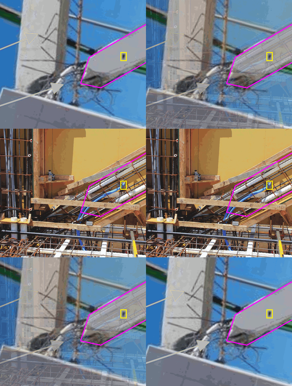
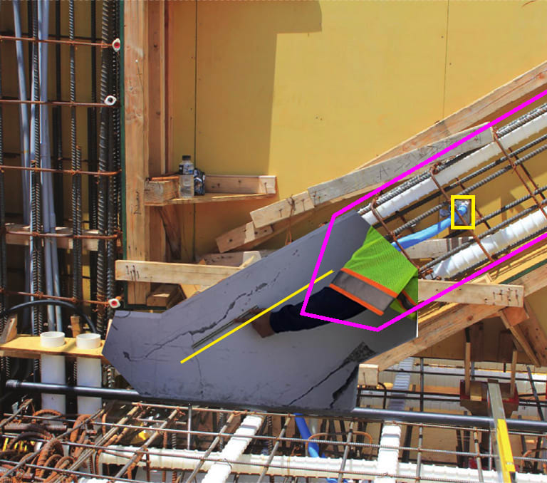
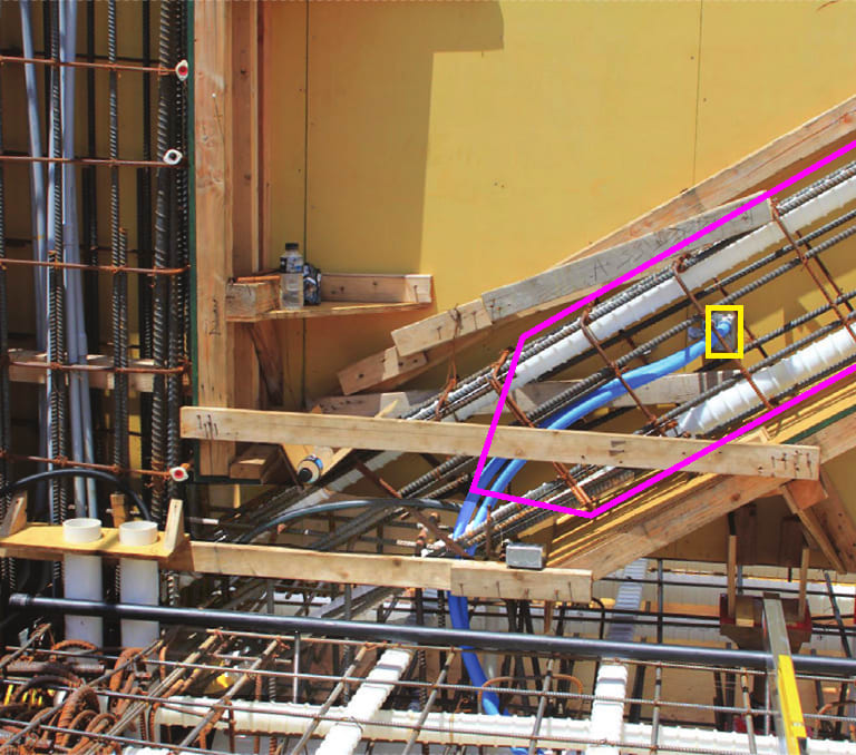
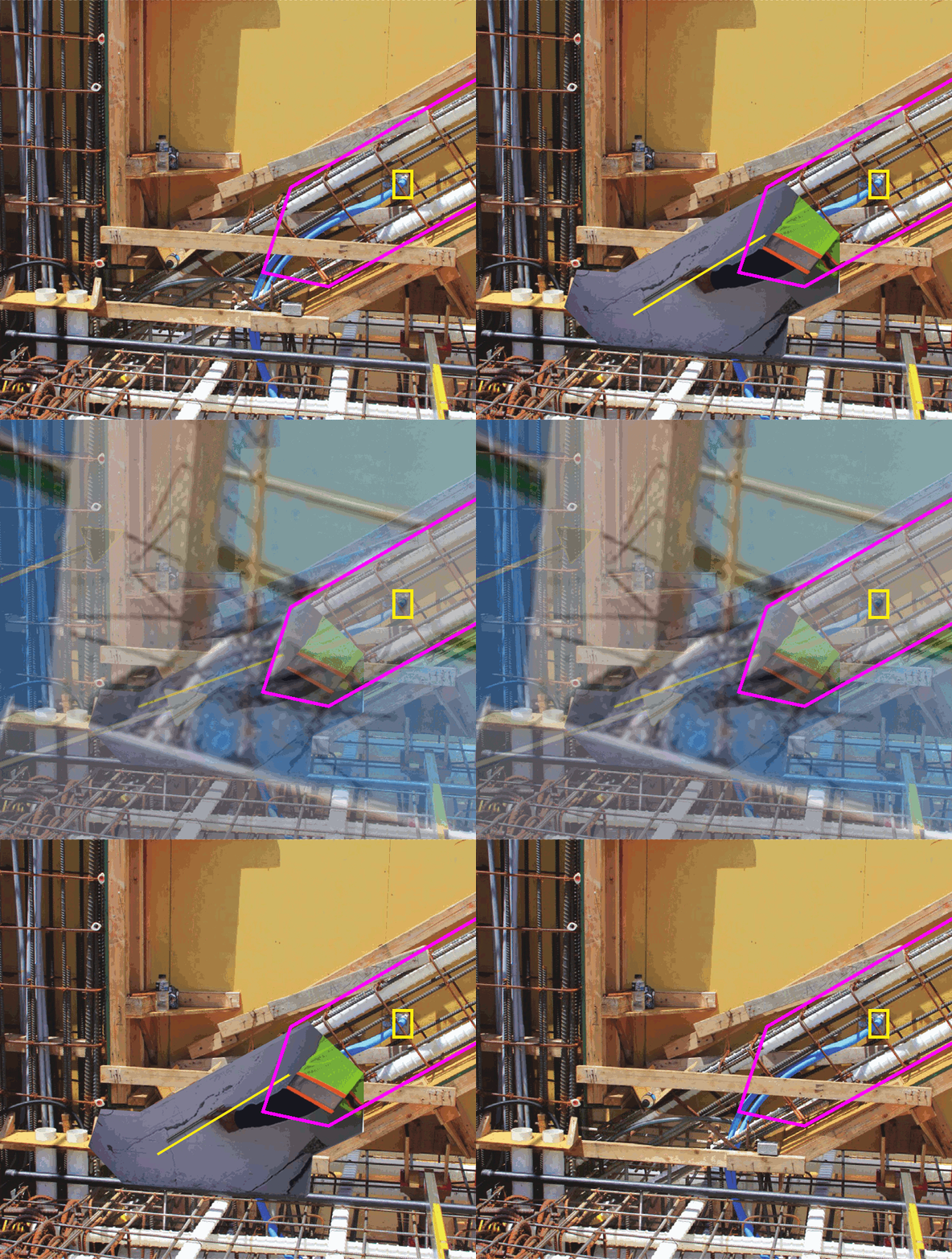
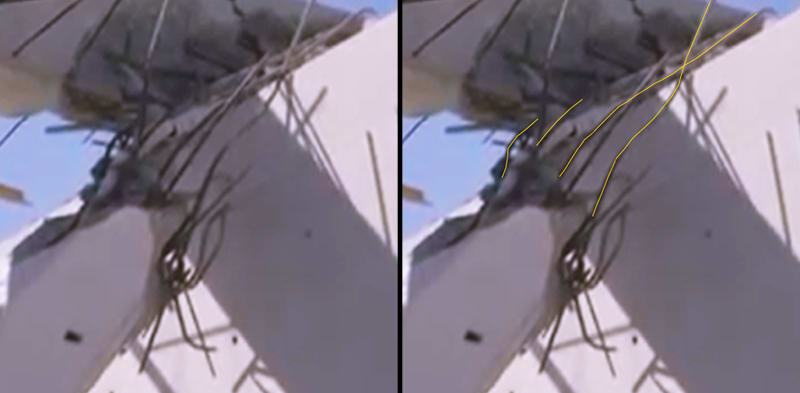
I found a point of reference for the damaged lower portion of Member 11, the electrical box on the east face of the member. Even a loose overlay is very indicative of the failure progression of the diagonal.

Electrical_Outlet.03.a_np3y52.jpg


Electrical_Outlet.03.b_acmuce.jpg


Electrical_Outlet.03.b.00_n9xpts.gif


Electrical_Outlet.03.d_tkwlso.jpg


The structure was designed anticipating a negative camber, even with the post tensioning system. The natural forces pull the base of the columns at either end toward the middle of the span while the stiffness of the end columns and the outward force of the diagonal members resist. Much effort has been invested in analyzing the structure through the frame of reference of the outward/downward force transmitted by the diagonal even in the face of obvious complications such as the portion of deck directly beneath Member 11 suffering minimal damage through the collapse. A much easier analysis can be done by examining the system through the frame of reference of the tension force exerted at the node by the deck, the question becoming "Is the deck adequately tied to the node"?

The obvious answer is no. The explanation quickly moves to the portion of slab beneath Member 12 which is isolated from the larger slab by a number of inclusions including four white ducts for future tie downs, six blue electrical conduits (three on either side), perhaps a grout line or two, and also the PT anchor plate for the lower PT rod. The deck rebar passing through the portion of slab beneath Member 12 is minimal. This isolation sets up the failure. If the slab is not a cohesive unit passing beneath Member 12, the only connection it has to the node is through the footprint of Member 11. The rebar, largely oriented as dowels are not optimized to resist the horizontal force. Even 300 percent more steel would not resist the destructive force of the tension in the deck. In fact, since the system ceased functioning as a cohesive unit, these very rebar are now serving to tear Member 11 apart with the base of 11 being pulled down and south with the deck. As the lower PT rod is retensioned, it cannot restore the structure but instead becomes the leveraging force pushing the remaining 11/12 node north while pulling the end of the deck south and further displacing the mid span downwards. This vicious cycle exasperates the tearing at the base of Member 11 while at the same time distorting it across the longitudinal axis.

I'll throw this in here because there is no eloquent way to include it. Surface roughening is not an issue. The base of 11 was doing its damndest to resist moving with the slab but it had no choice. Although a slight gap opened up beneath 11, this is not evidence of the "sliding" that it's made out to be. More surface roughness would only improve the efficiency of the tearing mechanism.

As I've posted earlier, it seems that Member 11 was pushing hard against Member 12 when it finally gave out, causing the kink in the upper PT rod. It did not take more than a few inches of relative displacement between the deck and 11/12 to destroy 11 at the deck interface. As 11 fails and the structure starts to collapse, the pancaking 11 hammers at the node while the deck rotates the diaphragm causing 12 to skip off to the north. The rotational component is evidenced by the CW/CCW diagonal fracture pattern seen in the diaphragm (it is not the cause of the failure, it is the result of the failure).

OSHA got this much right, "There is no viable mechanism to capture the horizontal tensile forces from the diagonal 11 to the deck." This failure is not at all mystical and it certainly does not give rise to the loose and sensational blanket statement of a concrete "blow-out". The largest identifiable concrete remnant landed immediately adjacent the base of the north end of the supporting pier. The structure succumbed to deliberate ill conceived actions of irresponsible parties and fell straight down.

Two things I would have expected to hear from the NTSB study, mention of management techniques pertaining to the meeting on the morning of the collapse (akin to aviation cockpit management where a plurality of experience and ability is used as an advantage), and footprint stress analysis of the awkwardly loaded Member 11.

In closing, I'd like to say that ego is not the best face of the NTSB. Colombia is spelled, "C-O-L-O-M-B-I-A"!

Edit: Three things -> also discussion of the camber and its progression since the work crew was using it as a measure of caution.
edit: Four things -> a measure of how much extension was pulled on the upper and lower PT rods with the retensioning. It would not have been a straight forward exercise if the structure was reacting to the load while the crew was working on it. The upper PT rod may not have required as much pull if it was stretching while the lower was pulled and the lower may have gone slack while the upper was pulled.
 
Or maybe the top surface of the base of Member 11 failed first? Clearly the cracking exhibited on the east and west sides of Member 11 can be seen as the side longitudinal column rebar pushing out the skewed stirrup. All that space at the lower end of 11 was a problem. Once the rebar reaches the nodal block, it is once again safely tucked inside the nodal block stirrups. I think we are finally getting to the real answer.

Electrical_Outlet.10.A.100_olubgc.jpg


Electrical_Outlet.10.A.00_lgqw5r.jpg


Electrical_Outlet.10.CD.00_evsj5i.gif


Added: I notice now that there was a problem with the column rebar lap right at the skewed stirrup. The devil is in the details and the details are getting chewed up.
I'm struggling to make sense of the rebar a the bottom end of 11. Does anyone with rebar experience have any comments on the workmanship visible in the photo's?
 
Excellent graphics. Masterful work.
My comment about reinforcing at node 11/12 is simply there is too much happening in too little space.
As I see the construction drawings, the reinforcing requirements for Member 11 could have been easily interpreted two ways due to the presence of the PT rods. One interpretation would result in less than code minimum reinforcing for a compression member.
In either interpretation the member appears to be lightly reinforced, particularly considering its importance to the success of the structure.
 
Thank-you Vance for your generous comment. I can't seem to put this down. The public has not been well served. It does not help that this most basic explaination was left outstanding for well over 2 1/2 years. I should not have been the first to find it.

In the near future I will likely break down the rebar visible in this photo and check for any indications of improvements made prior to casting that other photos cover.
 
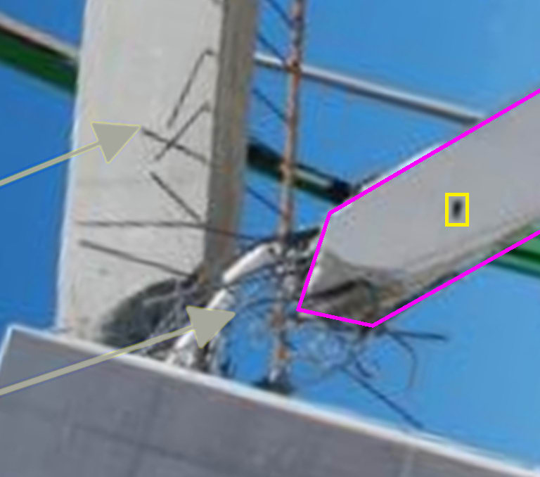
I'm not at my computer. I'll try to reference it asap. The sky shot of the damaged 11 is reversed left to right and rotated slightly. It is cropped from a broad view of the collapsed structure including the canopy and deck (on the ground). Look for big yellow arrows.

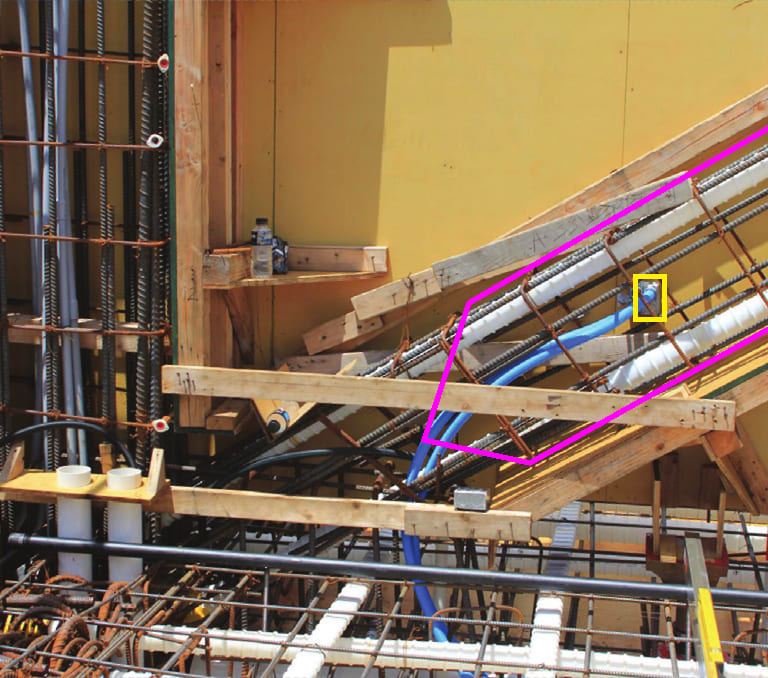
I was going through the Bridge Factors report from the NTSB database when I found the formwork photo, though that one is marked up. I see waross has included it earlier in this thread.

 
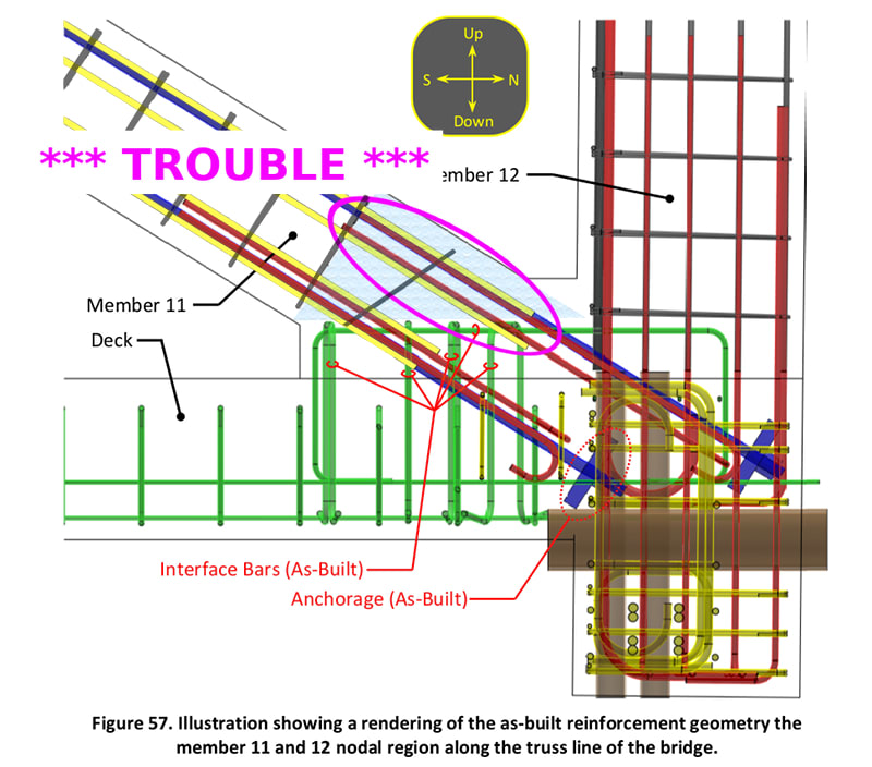
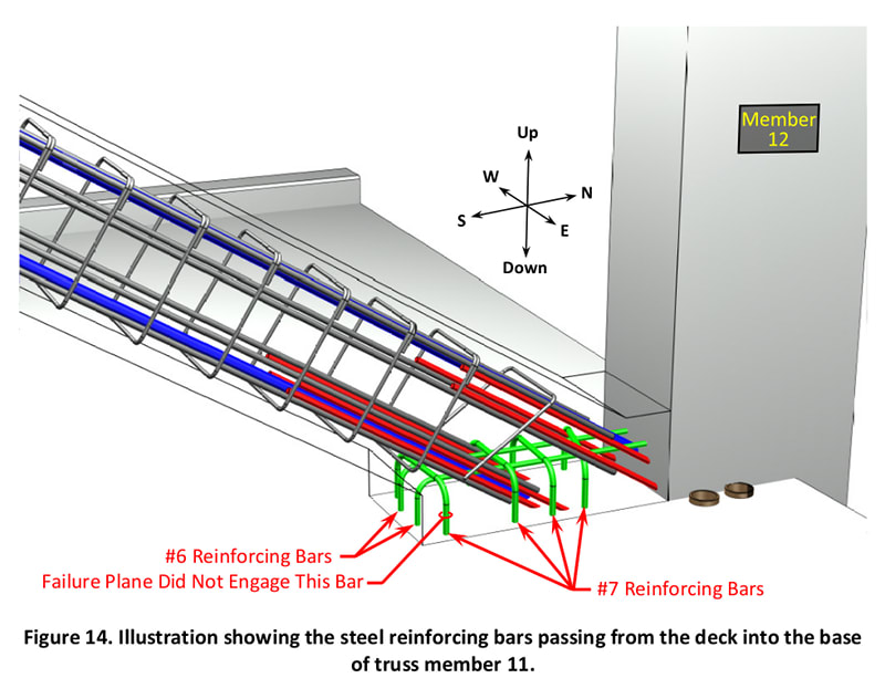
From the FHWA report, these figures are excellent representations of the as built situation. The skewed stirrup at the lower end of Member 11, just above the nodal block, is a U shaped tie that does not fully encompass the longitudinal rebar. As such, for the skyward portion of 11, neither the hooked bars rising from the nodal block, nor the longitudinal bars descending along 11, are fully invested in each other. Member 11 was a failure looking for an opportunity, today, tomorrow, or for whenever a crowd moved across the span.

FHWA_as_builg.02_cey88o.jpg


FHWA_as_builg.03_gizarg.jpg
 
SFCharlie (Computer) 28 Nov 20 20:23 said:
I don't seem to be able to find your top photo of the crushed member 11, do you have a reference handy?

The blue sky photo is from the OSHA report, the formwork photo is from the FIGG report (right click on the photo and copy gives a copy without the overlaying annotations), and the arm measuring is from the Bridge Factors Photo evidence. As I stated earlier, the OSHA image is flipped around, it is a view from the east overlaying a view from the west.

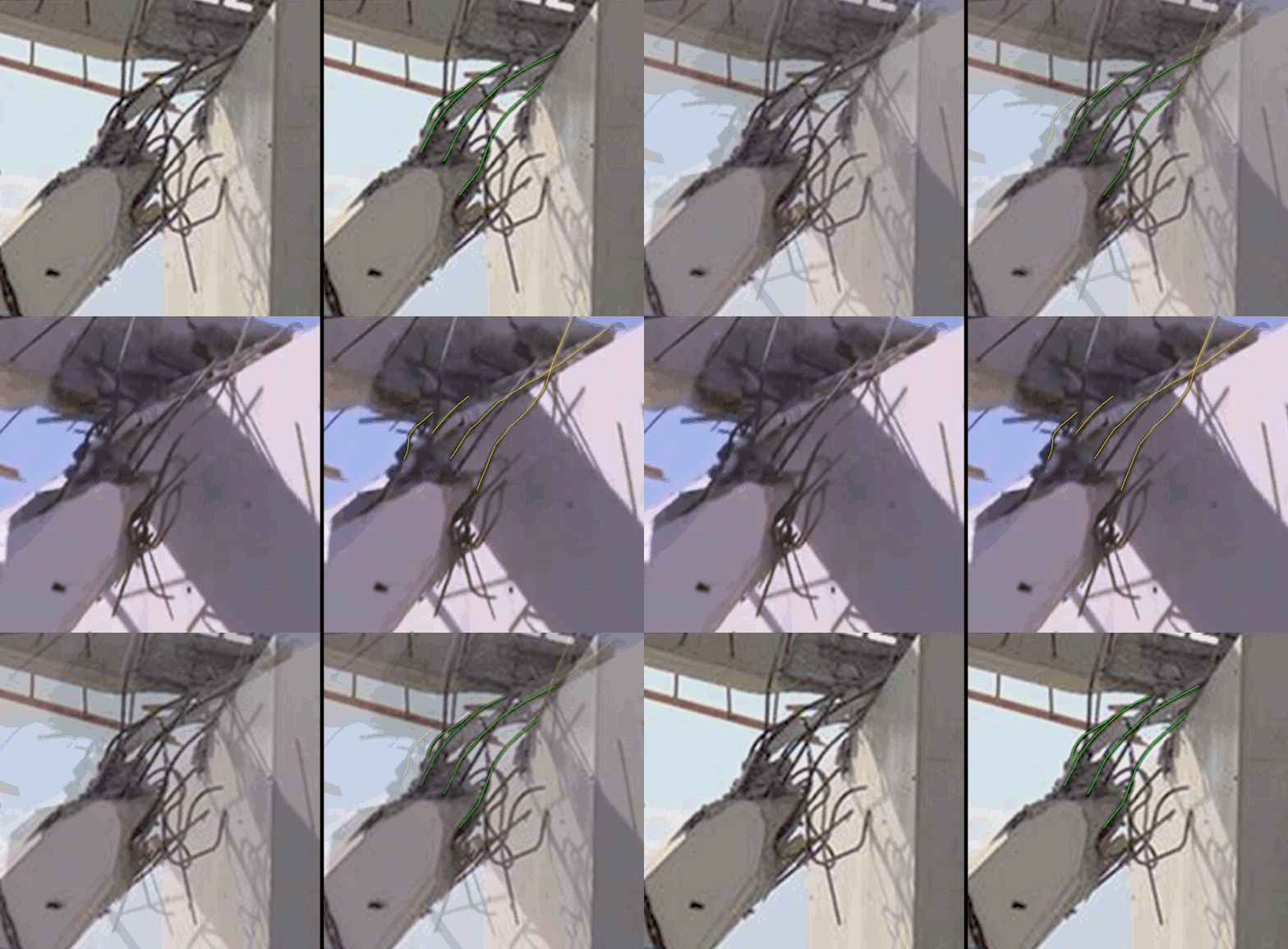
Now to explain the following, one image is from the NTSB B-roll video (the darker sky) and the other is from Materials Laboratory Factual Report - FHWA TFHRC Steel and Concrete Materials Testing. They are scaled and rotated slightly.

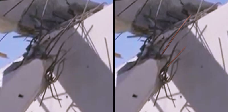
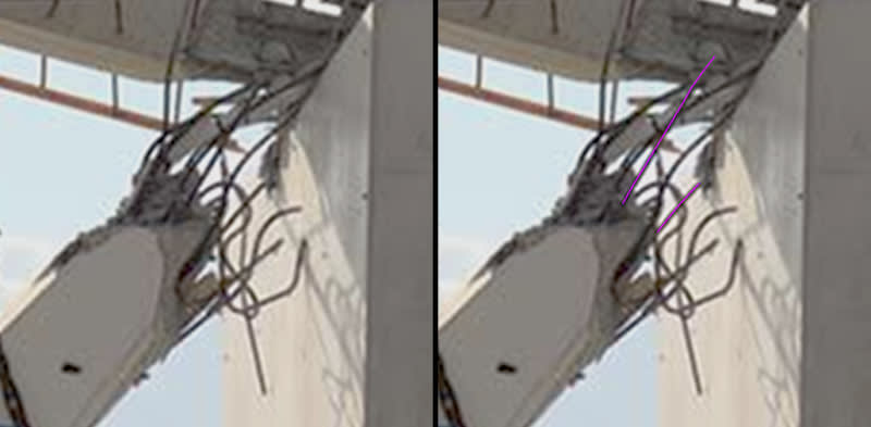
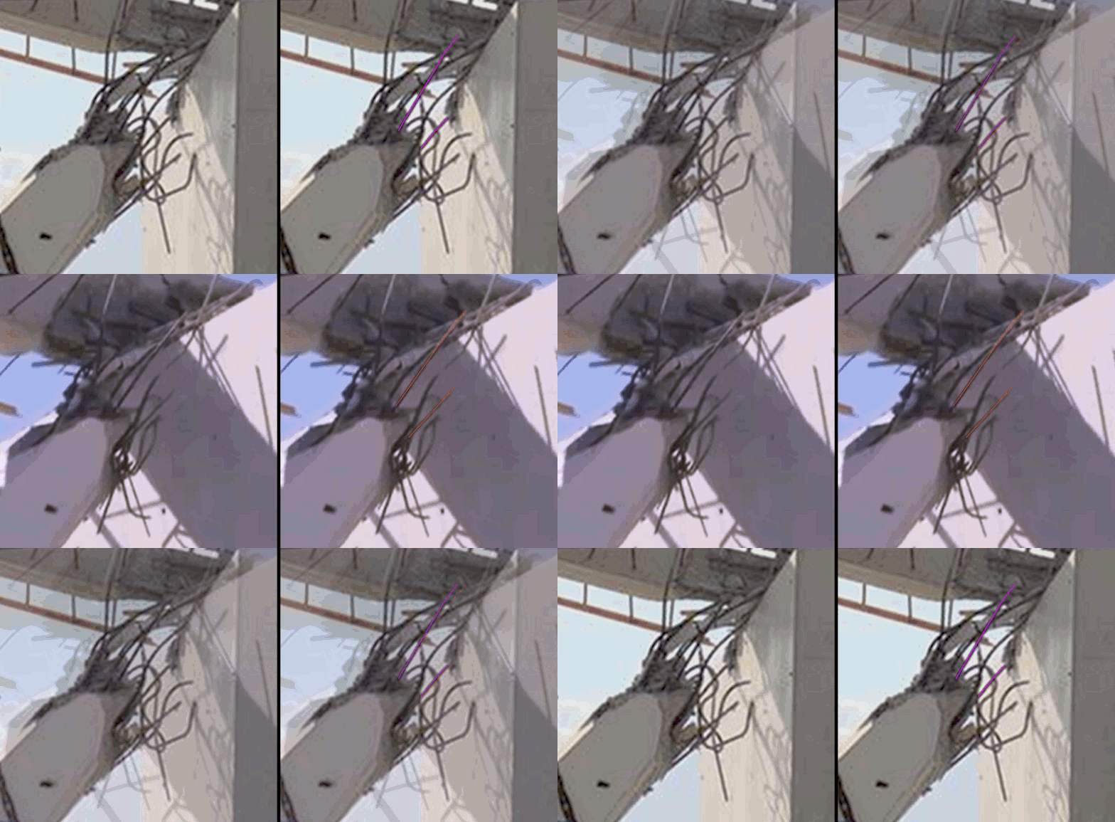
To borrow from Figure 57 in my above post, the two medial longitudinal rebar along the east face of Member 11 (that I have coloured yellow above, red-orange and hot pink below) seem to have escaped the collapse unscathed.

Comparison.202_e5bfxc.jpg


Comparison.204_tniopx.jpg


Comparison.202_inl1vk.gif


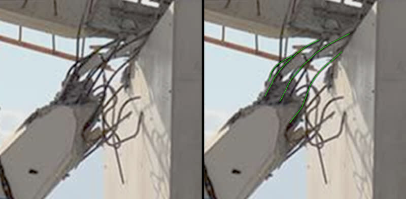
The J-hooks extending the member through the nodal block and slab along the east and skyward face (red above, green and yellow below) have assumed the displaced shape of the upper PT rod.

Comparison.101_zujstn.jpg


Comparison.103_foxpf2.jpg


Comparison.101_xs7iis.gif


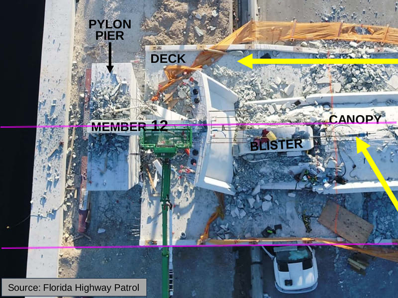
From the NTSB presentation, the following overhead image credited to the Florida Highway Patrol, indicates member 12 in its final position in alignment with the longitudinal axis of the deck. Member 11 however, has kicked out to the east. The exposed rebar on the west face of member 11 is significantly mangled. Together with my above post, it suggests to me that Member 11 buckled or sheared just above the nodal block with the upper portion moving east.

Aerial_of_Collapse.2_fm2wkx.jpg


To me there is no question that Member 12 held fast to the diaphragm while Member 11 pressed hard against it and failed. As these types of failure are know to be sudden, there was no indication, to even a seasoned observer, as Member 11 was overloaded with compression that morning. A clear hole blowout in Member 12, as suggested by OSHA, or any translational shear of Member 12, as is the unambiguous theme of many others, would not have allowed this damage to Member 11.

I estimate that there was a three foot length of Member 11 along its skyward face (see my above post) that was inadequately reinforced (missing hoops). It seems to have been an assembly difficulty that begged for a solution that was never found. In the end, this disaster should be seen as a colossal reinforcement design failure, though not for the dowelling issue cited by the NTSB.

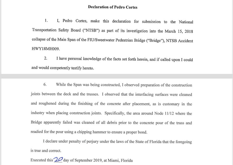
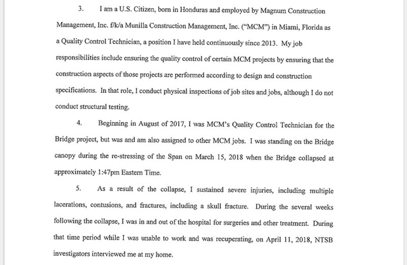
From the MCM Party Submission,

Declaration_q0bszr.jpg
 
It would be nice to know what items 3, 4 and 5 were...

Rather than think climate change and the corona virus as science, think of it as the wrath of God. Feel any better?

-Dik
 
Status
Not open for further replies.

Part and Inventory Search

Sponsor

Back
Top